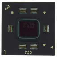
MPC755CRX400LE Freescale Semiconductor, MPC755CRX400LE Datasheet - Page 9

MPC755CRX400LE
Manufacturer Part Number
MPC755CRX400LE
Description
IC MPU 32BIT 400MHZ PPC 360-CBGA
Manufacturer
Freescale Semiconductor
Datasheet
1.MPC755BPX300LE.pdf
(56 pages)
Specifications of MPC755CRX400LE
Processor Type
MPC7xx PowerPC 32-Bit
Speed
400MHz
Voltage
2V
Mounting Type
Surface Mount
Package / Case
360-FCCBGA
Family Name
MPC7xx
Device Core
PowerPC
Device Core Size
64b
Frequency (max)
400MHz
Instruction Set Architecture
RISC
Supply Voltage 1 (typ)
2V
Operating Supply Voltage (max)
2.1V
Operating Supply Voltage (min)
1.9V
Operating Temp Range
0C to 105C
Operating Temperature Classification
Commercial
Mounting
Surface Mount
Pin Count
360
Package Type
FCCBGA
Lead Free Status / RoHS Status
Contains lead / RoHS non-compliant
Features
-
Lead Free Status / Rohs Status
Not Compliant
Available stocks
Company
Part Number
Manufacturer
Quantity
Price
Company:
Part Number:
MPC755CRX400LE
Manufacturer:
MOT
Quantity:
12 388
Company:
Part Number:
MPC755CRX400LE
Manufacturer:
Freescale Semiconductor
Quantity:
10 000
The MPC755 incorporates a thermal management assist unit (TAU) composed of a thermal sensor,
digital-to-analog converter, comparator, control logic, and dedicated special-purpose registers (SPRs). See
the MPC750 RISC Microprocessor Family User’s Manual for more information on the use of this feature.
Specifications for the thermal sensor portion of the TAU are found in
Freescale Semiconductor
Junction-to-ambient thermal resistance, natural
convection
Junction-to-ambient thermal resistance, natural
convection, four-layer (2s2p) board
Junction-to-ambient thermal resistance, 200 ft/min
airflow, single-layer (1s) board
Junction-to-ambient thermal resistance, 200 ft/min
airflow, four-layer (2s2p) board
Junction-to-board thermal resistance
Junction-to-case thermal resistance
Notes:
1. Junction temperature is a function of on-chip power dissipation, package thermal resistance, mounting site (board)
2. Per SEMI G38-87 and JEDEC JESD51-2 with the single layer board horizontal.
3. Per JEDEC JESD51-6 with the board horizontal.
4. Thermal resistance between the die and the printed circuit board per JEDEC JESD51-8. Board temperature is measured on
5. Thermal resistance between the die and the case top surface as measured by the cold plate method (MIL SPEC-883 Method
6. Refer to
temperature, ambient temperature, air flow, power dissipation of other components on the board, and board thermal
resistance.
the top surface of the board near the package.
1012.1) with the calculated case temperature. The actual value of R
Section 8.8, “Thermal Management Information,”
Characteristic
MPC755 RISC Microprocessor Hardware Specifications, Rev. 8
Table 4. Package Thermal Characteristics
Symbol
R
R
R
R
R
R
θ
θ
θ
θ
θ
θ
JMA
JMA
JMA
JC
JA
JB
for more details about thermal management.
MPC755
CBGA
θJC
<0.1
24
17
18
14
8
for the part is less than 0.1°C/W.
MPC755
Table
PBGA
Value
<0.1
31
25
25
21
17
6
Electrical and Thermal Characteristics
5.
MPC745
PBGA
<0.1
34
26
27
22
17
°C/W
°C/W
°C/W
°C/W
°C/W
°C/W
Unit
Notes
1, 2
1, 3
1, 3
1, 3
4
5
9


