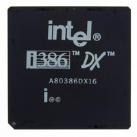
A80386DX16 Intel, A80386DX16 Datasheet - Page 62

A80386DX16
Manufacturer Part Number
A80386DX16
Description
IC MPU 32-BIT 5V 16MHZ 132-PGA
Manufacturer
Intel
Datasheet
1.A80386DX16.pdf
(139 pages)
Specifications of A80386DX16
Processor Type
386DX
Features
32-bit
Speed
16MHz
Voltage
5V
Mounting Type
Surface Mount
Package / Case
132-PGA
Family Name
Intel386 DX
Device Core Size
32b
Frequency (max)
16MHz
Supply Voltage 1 (typ)
5V
Operating Supply Voltage (max)
5.25V
Operating Supply Voltage (min)
4.75V
Operating Temp Range
0C to 85C
Operating Temperature Classification
Commercial
Mounting
Through Hole
Pin Count
132
Package Type
PGA
Lead Free Status / RoHS Status
Contains lead / RoHS non-compliant
Other names
807050
Available stocks
Company
Part Number
Manufacturer
Quantity
Price
Intel386
The signal descriptions sometimes refer to AC tim-
ing parameters such as ‘‘t
‘‘t
ters can be found in Tables 7-4 and 7-5
5 2 2 Clock (CLK2)
CLK2 provides the fundamental timing for the In-
tel386 DX It is divided by two internally to generate
the internal processor clock used for instruction exe-
cution The internal clock is comprised of two phas-
es ‘‘phase one’’ and ‘‘phase two ’’ Each CLK2 peri-
od is a phase of the internal clock Figure 5-2 illus-
trates the relationship If desired the phase of the
internal processor clock can be synchronized to a
known phase by ensuring the RESET signal falling
edge meets its applicable setup and hold times t
and t
5 2 3 Data Bus (D0 through D31)
These three-state bidirectional signals provide the
general purpose data path between the Intel386 DX
62
26
Reset Hold Time ’’ The values of these parame-
26
TM
DX MICROPROCESSOR
25
Figure 5-2 CLK2 Signal and Internal Processor Clock
Reset Setup Time’’ and
Figure 5-1 Functional Signal Groups
25
and other devices Data bus inputs and outputs indi-
cate ‘‘1’’ when HIGH The data bus can transfer data
on 32- and 16-bit buses using a data bus sizing fea-
ture controlled by the BS16
5 2 6 Bus Contol Data bus reads require that read
data setup and hold times t
correct operation In addition the Intel386 DX re-
quires that all data bus pins be at a valid logic state
(high or low) at the end of each read cycle when
READY
(and during halt cycles and shutdown cycles) the
Intel386 DX always drives all 32 signals of the data
bus even if the current bus size is 16-bits
5 2 4 Address Bus (BE0
These three-state outputs provide physical memory
addresses or I O port addresses The address bus
is capable of addressing 4 gigabytes of physical
memory space (00000000H through FFFFFFFFH)
and 64 kilobytes of I O address space (00000000H
through 0000FFFFH) for programmed I O I O
BE3
is asserted During any write operation
A2 through A31)
21
231630 – 1
and t
231630 –2
input See section
through
22
be met for


