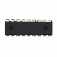
604-00050 Parallax Inc, 604-00050 Datasheet - Page 10

604-00050
Manufacturer Part Number
604-00050
Description
IC FLOATING-PT COPROC V3 18-DIP
Manufacturer
Parallax Inc
Datasheet
1.604-00050.pdf
(36 pages)
Specifications of 604-00050
Processor Type
Floating-Point Co-Processor
Voltage
2.7V ~ 5.5V
Mounting Type
Through Hole
Package / Case
*
Lead Free Status / RoHS Status
Lead free / RoHS Compliant
Features
-
Speed
-
Lead Free Status / RoHS Status
Lead free / RoHS Compliant, Lead free / RoHS Compliant
no additional delay is required. On faster microcontrollers a suitable delay must be inserted after a read instruction to
ensure that data is valid before the first byte is read.
Using OUT1 as a Ready/Busy Status
By default, the uM-FPU V3.1 chip outputs the Busy/Ready status on the SOUT pin, when the SOUT pin is not being
used for data input. Some microcontroller applications are not able to access this pin when the Busy/Ready status is
valid. As an alternative, the OUT1 pin can be configured as a Ready/Busy status (note: OUT1 is High for Ready and
Low for Busy). This is accomplished by programming bit 6 of mode parameter byte 0. See the section entitled Mode
- set mode parameters. When OUT1 is set to output the Ready/Busy status, the SOUT pin will no longer output the
Busy/Ready status. The OUT1 pin can also be used as an activity indicator by connected it to an LED with a pull-up
resistor.
Using the SERIN and SEROUT Pins
The SERIN and SEROUT pins provide a serial interface for the built-in Debug Monitor, and can also be used for
general purpose serial I/O when the Debug Monitor is not being used. The Debug Monitor communicates at 57,600
baud, using 8 data bits, no parity, one stop bit, and no flow control. The Debug Monitor is enabled if the SERIN pin
is high when the uM-FPU is Reset. Note: The idle state of an RS-232 connection will assert a high level on the
SERIN pin, so provided the uM-FPU is connected to an active idle RS-232 port when the uM-FPU is reset, the
Debug Monitor will be enabled. The SEROUT,0 instruction can also be used to enable/disable the Debug Monitor.
When the Debug Monitor is not being used, the serial I/O pins can be used for other purposes. The SEROUT,0
instruction is used to set the baud rate for the SERIN and SEROUT pins from 300 to 115,200 baud, using 8 data bits,
no parity, one stop bit, and no flow control. The SERIN instruction supports reading serial data from the SERIN pin,
and the SEROUT instruction supports sending serial data to the SEROUT pin. The uM-FPU V3.1 chip includes
support for NMEA sentence parsing, making it easy to connect to a GPS or other NMEA compliant device. The
serial output can be used to drive an LCD display or other serial device.
Micromega Corporation
1
2
3
4
5
6
7
8
9
/MCLR
AN0
AN1
CS
EXTIN
OSC1
OSC2
SEROUT
SERIN
uM-FPU V3
MAX232
SOUT/SCL
SIN/SDA
AVDD
SCLK
OUT0
OUT1
AVSS
VDD
VSS
18
17
16
15
14
13
12
11
10
10
DB-9 Female
5
4
3
2
1
Connecting to the uM-FPU V3.1
9
8
7
6
uM-FPU V3.1 Datasheet


