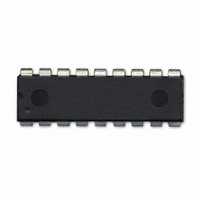
604-00050 Parallax Inc, 604-00050 Datasheet - Page 5

604-00050
Manufacturer Part Number
604-00050
Description
IC FLOATING-PT COPROC V3 18-DIP
Manufacturer
Parallax Inc
Datasheet
1.604-00050.pdf
(36 pages)
Specifications of 604-00050
Processor Type
Floating-Point Co-Processor
Voltage
2.7V ~ 5.5V
Mounting Type
Through Hole
Package / Case
*
Lead Free Status / RoHS Status
Lead free / RoHS Compliant
Features
-
Speed
-
Lead Free Status / RoHS Status
Lead free / RoHS Compliant, Lead free / RoHS Compliant
3-wire SPI interface
The 3-wire SPI connection uses separate data input and data output pins on the microcontroller. The CS pin is tied
low to select SPI mode at Reset, and must remain low during operation.
SPI Bus Interface
In order for the uM-FPU V3.1 chip to be used on a SPI bus with multiple devices, the CS pin must be enabled as a
chip select. This is accomplished by programming mode parameter bits stored in Flash memory on the uM-FPU
V3.1 chip. Bits 1:0 of mode parameter byte 0 must be set to 11 to select SPI bus mode. When this mode is set, the
SPI interface is automatically selected at Reset, and the CS pin is enabled as a standard active low slave select. The
SOUT pin is a tri-state output and is high impedance when the uM-FPU V3.1 chip is not selected. The connection
diagram is shown below:
Micromega Corporation
The clock signal is idle low and data is read on the rising edge of the clock (often referred to as SPI Mode 0).
Microcontroller Pins
Microcontroller Pins
DATA OUT
DATA IN
MISO
MOSI
SCK
/SS
CLK
VDD
VDD
3-wire SPI Connection
1
2
3
4
5
6
7
8
9
1
2
3
4
5
6
7
8
9
/MCLR
AN0
AN1
CS
EXTIN
OSC1
OSC2
SEROUT
SERIN
/MCLR
AN0
AN1
CS
EXTIN
OSC1
OSC2
SEROUT
SERIN
5
uM-FPU V3
uM-FPU V3
SOUT/SCL
SOUT/SCL
SIN/SDA
SIN/SDA
AVDD
AVDD
OUT0
OUT1
AVSS
SCLK
OUT0
OUT1
AVSS
SCLK
VDD
VDD
VSS
VSS
18
17
16
15
14
13
12
10
18
17
16
15
14
13
12
10
11
11
Connecting to the uM-FPU V3.1
VDD
VDD
uM-FPU V3.1 Datasheet


