BMR4540000/001 Ericsson Power Modules, BMR4540000/001 Datasheet - Page 23
BMR4540000/001
Manufacturer Part Number
BMR4540000/001
Description
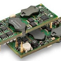
DC/DC Converters & Regulators 12V 20A 240W Bus Converter
Manufacturer
Ericsson Power Modules
Datasheet
1.BMR4540000001.pdf
(33 pages)
Specifications of BMR4540000/001
Output Power
240 W
Input Voltage Range
36 V to 75 V
Output Voltage (channel 1)
12 V
Output Current (channel 1)
20 A
Lead Free Status / Rohs Status
Lead free / RoHS Compliant


E
Operating information
Input Voltage
The input voltage range 36 to 75Vdc meets the requirements
of the European Telecom Standard ETS 300 132-2 for normal
input voltage range in –48 and –60 Vdc systems,
-40.5 to -57.0 V and –50.0 to -72 V respectively.
At input voltages exceeding 75 V, the power loss will be higher
than at normal input voltage and T
absolute max +125°C. The absolute maximum continuous
input voltage is 80 Vdc.
Turn-off Input Voltage
The product monitors the input voltage and will turn on and
turn off at predetermined levels. The turn on and turn off level
and the hysteresis in between can be configured via the
PMBus. The default hysteresis between turn on and turn off
input voltage is set to 2 V.
Remote Control (RC)
The maximum required sink current is 0.7 mA. When the RC
pin is left open, the voltage generated on the RC pin is
max 6 V. The logic options for the primary remote control is
configured using the PMBus. The default setting is negative
logic.
Remote Control (secondary side)
The CTRL CS pin can be configured as remote control via the
PMBus interface. In the default configuration the CTRL CS pin
is disabled and the output has an internal pull-up to 3.3V. The
CTRL CS pin can be left open when not used. The logic
options for the secondary remote control can be positive or
negative logic.
Input and Output Impedance
The impedance of both the input source and the load will
interact with the impedance of the product. It is important that
the input source has low characteristic impedance. Minimum
recommended external input capacitance is 100 uF. The
performance in some applications can be enhanced by
addition of external capacitance as described under External
Decoupling Capacitors.
Prepared (also subject responsible if other)
EMAOLII
Approved
SEC/D (Julia You)
BMR454 series Fully regulated Intermediate Bus Converters
Input 36-75 V, Output up to 40 A / 240 W
The products are fitted with a
configurable remote control function
on the primary and secondary side.
The primary remote control is
referenced to the primary negative
input connection (-In). The RC
function allows the converter to be
turned on/off by an external device
like a semiconductor or mechanical
switch. The RC pin has an internal
pull up resistor. The remote control
functions can also be configured
using the PMBus.
P1
must be limited to
Checked
EGUHAIL
Ericsson Internal
PRODUCT SPECIFICATION
No.
30/1301-BMR 454 Uen
Date
2011-05-05
External Decoupling Capacitors
When powering loads with significant dynamic current
requirements, the voltage regulation at the point of load can
be improved by addition of decoupling capacitors at the load.
The recommended minimum capacitance on the output is 100
uF. The most effective technique is to locate low ESR ceramic
and electrolytic capacitors as close to the load as possible,
using several parallel capacitors to lower the effective ESR.
The ceramic capacitors will handle high-frequency dynamic
load changes while the electrolytic capacitors are used to
handle low frequency dynamic load changes. Ceramic
capacitors will also reduce any high frequency noise across
the load.
It is equally important to use low resistance and low
inductance PWB layouts and cabling.
External decoupling capacitors will become part of the control
loop of the product and may affect the stability margins. As a
“rule of thumb”, 100 µF/A of output current can be added
without any additional analysis. The ESR of the capacitors is a
very important parameter. Power Modules guarantee stable
operation with a verified ESR value of >10 mΩ across the
output connections.
For further information please contact your local Ericsson
Power Modules representative.
Parallel Operation
The products can be paralleled for redundancy if external
oring diodes are used in series with the output.
PMBus configuration and support
The products provide a PMBus digital interface that enables
the user to configure many aspects of the device operation as
well as monitor the input and output parameters. Please
contact your local Ericsson Power Modules representative for
appropriate SW tools to down-load new configurations.
Output Voltage Adjust using PMBus
The output voltage of the product can be reconfigured using
the PMBus interface. Both BMR 454 0000/XXX and BMR 454
0004/005 can be adjusted from 8.1V to 13.2V. However, if
output voltages above 11V are desired at full load and at input
below 40V, the BMR4540004/005 should be used. When
output voltages below 11V are desired or the limited input
range (40-75V) is acceptable, the BMR4540000/XXX is
recommended for better efficiency and thermal performance.
The BMR 454 0002/XXX can be adjusted from 3.0V to 6.7V at
input voltages from 36V to 75V.
Margin Up/Down Controls
These controls allow the output voltage to be momentarily
adjusted, either up or down, by a nominal 10 %. This provides
a convenient method for dynamically testing the operation of
the load circuit over its supply margin or range. It can also be
used to verify the function of supply voltage supervisors.
The margin up and down levels of the product can be re-
configured using the PMBus interface.
Technical Specification
EN/LZT 146 404 R4B May 2011
© Ericsson AB
Rev
E
Reference
2 (6)
23
Related parts for BMR4540000/001
Image
Part Number
Description
Manufacturer
Datasheet
Request
R

Part Number:
Description:
37.5-150W DC/DC POWER MODULES
Manufacturer:
Ericsson Power Modules
Part Number:
Description:
DC/DC Power Supply Dual-OUT 3.3V/5V 9.6A/6.4A 40W 10-Pin
Manufacturer:
Ericsson Power Modules
Part Number:
Description:
DC/DC Power Supply Single-OUT 3.3V 20A 66W 8-Pin Quarter-Brick
Manufacturer:
Ericsson Power Modules
Datasheet:
Part Number:
Description:
DC/DC Power Supply Single-OUT 1.8V 50A 90W 11-Pin
Manufacturer:
Ericsson Power Modules
Part Number:
Description:
Module DC-DC 1-OUT 1.8V 30A 54W 9-Pin
Manufacturer:
Ericsson Power Modules

Part Number:
Description:
Module DC-DC 1-OUT 1.8V 60A 108W 11-Pin Half-Brick
Manufacturer:
Ericsson Power Modules
Datasheet:

Part Number:
Description:
Module DC-DC 1-OUT 12V 25A 300W 11-Pin Half-Brick
Manufacturer:
Ericsson Power Modules
Part Number:
Description:
Module DC-DC 1-OUT 5V 20A 100W Quarter-Brick
Manufacturer:
Ericsson Power Modules

Part Number:
Description:
Module DC-DC 1-OUT 12V 6A 72W 8-Pin 1/8-Brick
Manufacturer:
Ericsson Power Modules
Datasheet:
Part Number:
Description:
Module DC-DC 1-OUT 5.05V 2A 10W 18-Pin SMD
Manufacturer:
Ericsson Power Modules
Part Number:
Description:
Manufacturer:
Ericsson Power Modules
Datasheet:

Part Number:
Description:
Module DC-DC 1-OUT 5V 60A 300W 11-Pin Half-Brick Tray
Manufacturer:
Ericsson Power Modules
Part Number:
Description:
Module DC-DC 1-OUT 12V 1A 12W 18-Pin
Manufacturer:
Ericsson Power Modules
Datasheet:
Part Number:
Description:
Module DC-DC 2-OUT 12V/-12V 0.25A 6W 18-Pin SMD
Manufacturer:
Ericsson Power Modules
Part Number:
Description:
Module DC-DC 1-OUT 28V 11A 310W 11-Pin Half-Brick Tray
Manufacturer:
Ericsson Power Modules
Datasheet: