BMR4540000/001 Ericsson Power Modules, BMR4540000/001 Datasheet - Page 25
BMR4540000/001
Manufacturer Part Number
BMR4540000/001
Description
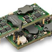
DC/DC Converters & Regulators 12V 20A 240W Bus Converter
Manufacturer
Ericsson Power Modules
Datasheet
1.BMR4540000001.pdf
(33 pages)
Specifications of BMR4540000/001
Output Power
240 W
Input Voltage Range
36 V to 75 V
Output Voltage (channel 1)
12 V
Output Current (channel 1)
20 A
Lead Free Status / Rohs Status
Lead free / RoHS Compliant


Thermal Consideration
General
The products are designed to operate in different thermal
environments and sufficient cooling must be provided to
ensure reliable operation.
For products mounted on a PWB without a heat sink attached,
cooling is achieved mainly by conduction, from the pins to the
host board, and convection, which is dependant on the airflow
across the product. Increased airflow enhances the cooling of
the product. The Output Current Derating graph found in the
Output section for each model provides the available output
current vs. ambient air temperature and air velocity at
V
The product is tested on a 254 x 254 mm, 35 µm (1 oz),
8-layer test board mounted vertically in a wind tunnel with a
cross-section of 608 x 203 mm.
Definition of product operating temperature
The product operating temperatures is used to monitor the
temperature of the product, and proper thermal conditions can
be verified by measuring the temperature at positions P1, P2
and P3. The temperature at these positions (T
should not exceed the maximum temperatures in the table
below. The number of measurement points may vary with
different thermal design and topology. Temperatures above
maximum T
allowed and may cause permanent damage.
E
Position
P1
P2
P3
P4
Prepared (also subject responsible if other)
EMAOLII
Approved
SEC/D (Julia You)
BMR454 series Fully regulated Intermediate Bus Converters
Input 36-75 V, Output up to 40 A / 240 W
I
= 53 V.
P1
Description
PCB (Reference point)
Opto-coupler
PCB (Output inductor)
Transformer core
, measured at the reference point P1 are not
Max Temperature
T
T
T
T
P1
P2
P3
P4
=125º C
=105º C
=125º C
=125º C
P1
, T
Checked
EGUHAIL
P2
and T
P3
)
(Best airflow direction right to left.)
Ambient Temperature Calculation
For products with base plate the maximum allowed ambient
temperature can be calculated by using the thermal resistance.
1. The power loss is calculated by using the formula
((1/η) - 1) × output power = power losses (Pd).
η = efficiency of product. E.g. 95% = 0.95
2. Find the thermal resistance (Rth) in the Thermal Resistance
graph found in the Output section for each model. Note that
the thermal resistance can be significantly reduced if a
heat sink is mounted on the top of the base plate.
Calculate the temperature increase (T).
3. Max allowed ambient temperature is:
Max T
E.g. BMR 454 0100/001 at 1m/s:
1.
2. 15.3 W × 4.1°C/W = 63°C
3. 125 °C - 63°C = max ambient temperature is 62°C
The actual temperature will be dependent on several factors
such as the PCB size, number of layers and direction of
airflow.
Ericsson Internal
PRODUCT SPECIFICATION
No.
30/1301-BMR 454 Uen
Date
2011-05-05
T = Rth x Pd
((
0.94
P1
1
- T.
) -
Top view
1) × 240 W = 15.3 W
Technical Specification
EN/LZT 146 404 R4B May 2011
© Ericsson AB
Rev
E
P2
P3
P1
Reference
Bottom view
P4
4 (6)
25
Related parts for BMR4540000/001
Image
Part Number
Description
Manufacturer
Datasheet
Request
R

Part Number:
Description:
37.5-150W DC/DC POWER MODULES
Manufacturer:
Ericsson Power Modules
Part Number:
Description:
DC/DC Power Supply Dual-OUT 3.3V/5V 9.6A/6.4A 40W 10-Pin
Manufacturer:
Ericsson Power Modules
Part Number:
Description:
DC/DC Power Supply Single-OUT 3.3V 20A 66W 8-Pin Quarter-Brick
Manufacturer:
Ericsson Power Modules
Datasheet:
Part Number:
Description:
DC/DC Power Supply Single-OUT 1.8V 50A 90W 11-Pin
Manufacturer:
Ericsson Power Modules
Part Number:
Description:
Module DC-DC 1-OUT 1.8V 30A 54W 9-Pin
Manufacturer:
Ericsson Power Modules

Part Number:
Description:
Module DC-DC 1-OUT 1.8V 60A 108W 11-Pin Half-Brick
Manufacturer:
Ericsson Power Modules
Datasheet:

Part Number:
Description:
Module DC-DC 1-OUT 12V 25A 300W 11-Pin Half-Brick
Manufacturer:
Ericsson Power Modules
Part Number:
Description:
Module DC-DC 1-OUT 5V 20A 100W Quarter-Brick
Manufacturer:
Ericsson Power Modules

Part Number:
Description:
Module DC-DC 1-OUT 12V 6A 72W 8-Pin 1/8-Brick
Manufacturer:
Ericsson Power Modules
Datasheet:
Part Number:
Description:
Module DC-DC 1-OUT 5.05V 2A 10W 18-Pin SMD
Manufacturer:
Ericsson Power Modules
Part Number:
Description:
Manufacturer:
Ericsson Power Modules
Datasheet:

Part Number:
Description:
Module DC-DC 1-OUT 5V 60A 300W 11-Pin Half-Brick Tray
Manufacturer:
Ericsson Power Modules
Part Number:
Description:
Module DC-DC 1-OUT 12V 1A 12W 18-Pin
Manufacturer:
Ericsson Power Modules
Datasheet:
Part Number:
Description:
Module DC-DC 2-OUT 12V/-12V 0.25A 6W 18-Pin SMD
Manufacturer:
Ericsson Power Modules
Part Number:
Description:
Module DC-DC 1-OUT 28V 11A 310W 11-Pin Half-Brick Tray
Manufacturer:
Ericsson Power Modules
Datasheet: