BMR4540000/001 Ericsson Power Modules, BMR4540000/001 Datasheet - Page 24
BMR4540000/001
Manufacturer Part Number
BMR4540000/001
Description
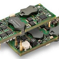
DC/DC Converters & Regulators 12V 20A 240W Bus Converter
Manufacturer
Ericsson Power Modules
Datasheet
1.BMR4540000001.pdf
(33 pages)
Specifications of BMR4540000/001
Output Power
240 W
Input Voltage Range
36 V to 75 V
Output Voltage (channel 1)
12 V
Output Current (channel 1)
20 A
Lead Free Status / Rohs Status
Lead free / RoHS Compliant


E
Operating information continued
Soft-start Power Up
The soft-start control introduces a time-delay (default setting
40 ms) before allowing the output voltage to rise. The default
rise time of the ramp up is 10 ms. Power-up is hence
completed within 50 ms in default configuration using remote
control. When starting by applying input voltage the control
circuit boot-up time adds an additional 100 ms delay. The soft-
start power up of the product can be reconfigured using the
PMBus interface.
Remote Sense
The products have remote sense that can be used to
compensate for voltage drops between the output and the
point of load. The sense traces should be located close to the
PCB ground layer to reduce noise susceptibility. The remote
sense circuitry will compensate for up to 10% voltage drop
between +Out pin and the point of load (+Sense). –Sense pin
should be connected to –Out and can not be used as remote
sense. If the remote sense is not needed +Sense should be
connected to +Out. To be able to use remote sense the
converter must be equipped with a digital connector.
Temperature Protection (OTP, UTP)
The products are protected from thermal overload by an
internal temperature shutdown protection.
When T
exceeded the product will shut down. The product will make
continuous attempts to start up (non-latching mode) and
resume normal operation automatically when the temperature
has dropped below the temperature threshold, the hysteresis
is defined in general electrical specification.
The OTP and hysteresis of the product can be re-configured
using the PMBus interface. The product has also an under
temperature protection. The OTP and UTP fault limit and fault
response can be configured via the PMBus. Note: using the
fault response “continue without interruption” may cause
permanent damage of the product.
Over Voltage Protection (OVP)
The product has output over voltage protection that will shut
down the converter in over voltage conditions (latching mode)
The OVP fault level and fault response can be re-configured
using the PMBus interface.
Over Current Protection (OCP)
The product includes current limiting circuitry for protection at
continuous overload. The product will enter hic-up mode if the
maximum output current is exceeded and the output voltage is
below 0.3×Vout. The load distribution should be designed for
the maximum output short circuit current specified. The OCP
level and fault response can be re-configured using the
PMBus interface. The default OCP configuration is set to hic-
up mode for the over current protection.
Prepared (also subject responsible if other)
EMAOLII
Approved
SEC/D (Julia You)
BMR454 series Fully regulated Intermediate Bus Converters
Input 36-75 V, Output up to 40 A / 240 W
P1
as defined in thermal consideration section is
Checked
EGUHAIL
Ericsson Internal
PRODUCT SPECIFICATION
No.
30/1301-BMR 454 Uen
Date
2011-05-05
Input Over/Under voltage protection
The input of the product can be protected agains high input
voltage and low input voltage. The over- and under-voltage
fault level and fault response can be configured via the PMBus
interface.
Pre-bias Start-up
The product has a Pre-bias start up functionality and will not
sink current during start up if a pre-bias source is present at
the output terminals.
Synchronization
When the PG SYNC pin is configured as an input (SYNC IN)
the device will automatically check for a clock signal on the
PG SYNC pin each time the module is enabled by RC or via
PMBus. The incoming clock signal must be 150, 200 or
250kHz and must be stable when the module is enabled.
Note that PG SYNC pin is by default configured as Power
Good output but may be reconfigured to SYNC IN via the
PMBus interface.
Power Good
The PG SYNC pin is by default configured as Power Good
output. The power good signal (TTL level) indicates proper
operation of the product and can also be used as an error flag
indicator. The Power Good signal is by default configured as
active low and can be re-configured via the PMBus interface.
Tracking and External reference
The PG SYNC pin can be configured as an input for voltage
tracking or an external analogue reference.
The PG SYNC pin is configured via the PMBus interface and
has default setting Power Good.
Switching frequency adjust using PMBus
The switching frequency is set to 180 kHz as default but this
can be reconfigured via the PMBus interface. The product is
optimized at this frequency but can run at lower and higher
frequency, (150 kHz – 250 kHz). The electrical performance
can be affected if the switching frequency is changed.
Input Transient
The BMR454 products have limited ability to react on sudden
input voltage changes. As an example the 12V module
BMR454xxxx/001 can have an output voltage deviation of 5V
when a 20V input step is applied (40V to 60V). This is tested
with a slew rate of 0.1V/us on the input voltage change and
minimum output capacitance 100uF. Increasing the output
capacitance will improve the result.
Technical Specification
EN/LZT 146 404 R4B May 2011
© Ericsson AB
Rev
E
Reference
3 (6)
24
Related parts for BMR4540000/001
Image
Part Number
Description
Manufacturer
Datasheet
Request
R

Part Number:
Description:
37.5-150W DC/DC POWER MODULES
Manufacturer:
Ericsson Power Modules
Part Number:
Description:
DC/DC Power Supply Dual-OUT 3.3V/5V 9.6A/6.4A 40W 10-Pin
Manufacturer:
Ericsson Power Modules
Part Number:
Description:
DC/DC Power Supply Single-OUT 3.3V 20A 66W 8-Pin Quarter-Brick
Manufacturer:
Ericsson Power Modules
Datasheet:
Part Number:
Description:
DC/DC Power Supply Single-OUT 1.8V 50A 90W 11-Pin
Manufacturer:
Ericsson Power Modules
Part Number:
Description:
Module DC-DC 1-OUT 1.8V 30A 54W 9-Pin
Manufacturer:
Ericsson Power Modules

Part Number:
Description:
Module DC-DC 1-OUT 1.8V 60A 108W 11-Pin Half-Brick
Manufacturer:
Ericsson Power Modules
Datasheet:

Part Number:
Description:
Module DC-DC 1-OUT 12V 25A 300W 11-Pin Half-Brick
Manufacturer:
Ericsson Power Modules
Part Number:
Description:
Module DC-DC 1-OUT 5V 20A 100W Quarter-Brick
Manufacturer:
Ericsson Power Modules

Part Number:
Description:
Module DC-DC 1-OUT 12V 6A 72W 8-Pin 1/8-Brick
Manufacturer:
Ericsson Power Modules
Datasheet:
Part Number:
Description:
Module DC-DC 1-OUT 5.05V 2A 10W 18-Pin SMD
Manufacturer:
Ericsson Power Modules
Part Number:
Description:
Manufacturer:
Ericsson Power Modules
Datasheet:

Part Number:
Description:
Module DC-DC 1-OUT 5V 60A 300W 11-Pin Half-Brick Tray
Manufacturer:
Ericsson Power Modules
Part Number:
Description:
Module DC-DC 1-OUT 12V 1A 12W 18-Pin
Manufacturer:
Ericsson Power Modules
Datasheet:
Part Number:
Description:
Module DC-DC 2-OUT 12V/-12V 0.25A 6W 18-Pin SMD
Manufacturer:
Ericsson Power Modules
Part Number:
Description:
Module DC-DC 1-OUT 28V 11A 310W 11-Pin Half-Brick Tray
Manufacturer:
Ericsson Power Modules
Datasheet: