BMR4540000/001 Ericsson Power Modules, BMR4540000/001 Datasheet - Page 27
BMR4540000/001
Manufacturer Part Number
BMR4540000/001
Description
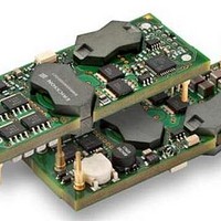
DC/DC Converters & Regulators 12V 20A 240W Bus Converter
Manufacturer
Ericsson Power Modules
Datasheet
1.BMR4540000001.pdf
(33 pages)
Specifications of BMR4540000/001
Output Power
240 W
Input Voltage Range
36 V to 75 V
Output Voltage (channel 1)
12 V
Output Current (channel 1)
20 A
Lead Free Status / Rohs Status
Lead free / RoHS Compliant


E
PMBus Communications
The products provide a PMBus digital interface that enables
the user to configure many aspects of the device operation as
well as monitor the input and output parameters. The products
can be used with any standard two-wire I
device. In addition, the device is compatible with PMBus
version 1.1 and includes an SALERT line to help mitigate
bandwidth limitations related to continuous fault monitoring.
Monitoring via PMBus
A system controller can monitor a wide variety of different
parameters through the PMBus interface. The controller can
monitor for fault condition by monitoring the SALERT pin,
which will be asserted when any number of pre-configured
fault or warning conditions occur. The system controller can
also continuously monitor for any number of power conversion
parameters including but not limited to the following:
•
•
•
•
•
•
Evaluation software
A Configuration Monitoring and Management (CMM)
evaluation software, is available for the products.
For more information please contact your local
Ericsson Power Modules sales representative.
Addressing
The figure and table below show recommended resistor
values with min and max voltage range for hard-wiring PMBus
addresses (series E96, 1% tolerance resistors suggested):
Prepared (also subject responsible if other)
SECSUND
Approved
EAB/FJB/GMF (Ksenia Harrisen)
BMR454 series Fully regulated Intermediate Bus Converters
Input 36-75 V, Output up to 40 A / 240 W
Input voltage
Output voltage
Output current
Internal junction temperature
Switching frequency
Duty cycle
2
C or SMBus host
Checked
(EANDKUL)
The SA0 and SA1 pins can be configured with a resistor to
GND according to the following equation.
If any one of those voltage applied to ADC0 and ADC1 is out
of the range from the table above, PMBus address 127 is
assigned. If the calculated PMBus address is 0 or 12, PMBus
address 127 is assigned instead. PMBus address 11 is not to
be used. The user shall also be aware of further limitations of
the addresses as stated in the PMBus Specification.
Ericsson Internal
PRODUCT SPECIFICATION
No.
31/1301-BMR 453+
Date
2011-03-23
SA0/SA1
0
1
2
3
4
5
6
7
PMBus Address = 8 x (SA0value) + (SA1 value)
R
1
/R
24.9
49.9
Technical Specification
EN/LZT 146 404 R4B May 2011
© Ericsson AB
100
124
150
174
200
Rev
A
75
0
[kΩ]
Min voltage[V]
Reference
0.261
0.524
0.749
0.926
1.065
1.187
1.285
1.371
Max voltage[V]
0.438
0.679
0.871
1.024
1.146
1.256
1.345
1.428
1 (4)
27
Related parts for BMR4540000/001
Image
Part Number
Description
Manufacturer
Datasheet
Request
R

Part Number:
Description:
37.5-150W DC/DC POWER MODULES
Manufacturer:
Ericsson Power Modules
Part Number:
Description:
DC/DC Power Supply Dual-OUT 3.3V/5V 9.6A/6.4A 40W 10-Pin
Manufacturer:
Ericsson Power Modules
Part Number:
Description:
DC/DC Power Supply Single-OUT 3.3V 20A 66W 8-Pin Quarter-Brick
Manufacturer:
Ericsson Power Modules
Datasheet:
Part Number:
Description:
DC/DC Power Supply Single-OUT 1.8V 50A 90W 11-Pin
Manufacturer:
Ericsson Power Modules
Part Number:
Description:
Module DC-DC 1-OUT 1.8V 30A 54W 9-Pin
Manufacturer:
Ericsson Power Modules

Part Number:
Description:
Module DC-DC 1-OUT 1.8V 60A 108W 11-Pin Half-Brick
Manufacturer:
Ericsson Power Modules
Datasheet:

Part Number:
Description:
Module DC-DC 1-OUT 12V 25A 300W 11-Pin Half-Brick
Manufacturer:
Ericsson Power Modules
Part Number:
Description:
Module DC-DC 1-OUT 5V 20A 100W Quarter-Brick
Manufacturer:
Ericsson Power Modules

Part Number:
Description:
Module DC-DC 1-OUT 12V 6A 72W 8-Pin 1/8-Brick
Manufacturer:
Ericsson Power Modules
Datasheet:
Part Number:
Description:
Module DC-DC 1-OUT 5.05V 2A 10W 18-Pin SMD
Manufacturer:
Ericsson Power Modules
Part Number:
Description:
Manufacturer:
Ericsson Power Modules
Datasheet:

Part Number:
Description:
Module DC-DC 1-OUT 5V 60A 300W 11-Pin Half-Brick Tray
Manufacturer:
Ericsson Power Modules
Part Number:
Description:
Module DC-DC 1-OUT 12V 1A 12W 18-Pin
Manufacturer:
Ericsson Power Modules
Datasheet:
Part Number:
Description:
Module DC-DC 2-OUT 12V/-12V 0.25A 6W 18-Pin SMD
Manufacturer:
Ericsson Power Modules
Part Number:
Description:
Module DC-DC 1-OUT 28V 11A 310W 11-Pin Half-Brick Tray
Manufacturer:
Ericsson Power Modules
Datasheet: