UDT020A0X3-SRZ Lineage Power, UDT020A0X3-SRZ Datasheet - Page 16
UDT020A0X3-SRZ
Manufacturer Part Number
UDT020A0X3-SRZ
Description
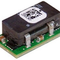
DC/DC Converters & Regulators 3-14.4Vin .6-5.5Vout 20A Neg SMT Digital
Manufacturer
Lineage Power
Datasheet
1.UDT020A0X3-SRZ.pdf
(39 pages)
Specifications of UDT020A0X3-SRZ
Product
Non-Isolated / POL
Input Voltage Range
3 VDC to 14.4 VDC
Input Voltage (nominal)
12 V
Output Voltage (channel 1)
0.6 VDC to 5.5 VDC
Output Current (channel 1)
20 A
Output Voltage
0.6 VDC to 5.5 VDC
Lead Free Status / Rohs Status
Lead free / RoHS Compliant


Preliminary Data Sheet
May 10, 2011
Output Voltage Sequencing
The power module includes a sequencing feature, EZ-
SEQUENCE that enables users to implement various
types of output voltage sequencing in their
applications. This is accomplished via an additional
sequencing pin. When not using the sequencing
feature, leave it unconnected.
The voltage applied to the SEQ pin should be scaled
down by the same ratio as used to scale the output
voltage down to the reference voltage of the module.
This is accomplished by an external resistive divider
connected across the sequencing voltage before it is
fed to the SEQ pin as shown in Fig. 44.
Figure 44. Circuit showing connection of the
sequencing signal to the SEQ pin.
When the scaled down sequencing voltage is applied
to the SEQ pin, the output voltage tracks this voltage
until the output reaches the set-point voltage. The final
value of the sequencing voltage must be set higher
than the set-point voltage of the module. The output
voltage follows the sequencing voltage on a one-to-
one basis. By connecting multiple modules together,
multiple modules can track their output voltages to the
voltage applied on the SEQ pin.
To initiate simultaneous shutdown of the modules, the
SEQ pin voltage is lowered in a controlled manner.
The output voltage of the modules tracks the voltages
below their set-point voltages on a one-to-one basis.
A valid input voltage must be maintained until the
tracking and output voltages reach ground potential.
Overcurrent Protection
To provide protection in a fault (output overload)
condition, the unit is equipped with internal
current-limiting circuitry and can endure current limiting
continuously. At the point of current-limit inception, the
unit enters hiccup mode. The unit operates normally
once the output current is brought back into its
specified range.
Digital Adjustable Overcurrent Warning
Please see the Digital Feature Descriptions
section.
Overtemperature Protection
To provide protection in a fault condition, the unit is
equipped with a thermal shutdown circuit. The unit will
LINEAGE
POWER
100 pF
V
R1=Rtrim
SEQ
20K
SEQ
DLynx Module
SIG_GND
20A Digital Micro DLynx
3 – 14.4Vdc input; 0.45Vdc to 5.5Vdc output; 20A output
shut down if the overtemperature threshold of
120
T
then wait to cool before attempting to restart.
Digital Temperature Status via PMBus
Please see the Digital Feature Descriptions
section.
Digitally Adjustable Output Over and Under
Voltage Protection
Please see the Digital Feature Descriptions
section.
Input Undervoltage Lockout
At input voltages below the input undervoltage lockout
limit, the module operation is disabled. The module
will begin to operate at an input voltage above the
undervoltage lockout turn-on threshold.
Digitally Adjustable Input Undervoltage
Lockout
Please see the Digital Feature Descriptions
section.
Digitally Adjustable Power Good Thresholds
Please see the Digital Feature Descriptions
section.
Synchronization
The module switching frequency can be synchronized
to a signal with an external frequency within a
specified range. Synchronization can be done by using
the external signal applied to the SYNC pin of the
module as shown in Fig. 45, with the converter being
synchronized by the rising edge of the external signal.
The Electrical Specifications table specifies the
requirements of the external SYNC signal. If the SYNC
pin is not used, the module should free run at the
default switching frequency. If synchronization is not
being used, connect the SYNC pin to GND.
Figure 45. External source connections to
synchronize switching frequency of the module.
Measuring Output Current, Output Voltage
and Input Voltage
Please see the Digital Feature Descriptions
section.
ref
TM
o
.Once the unit goes into thermal shutdown it will
: Non-isolated DC-DC Power Modules
C(typ) is exceeded at the thermal reference point
+
─
GND
SYNC
MODULE
16
Related parts for UDT020A0X3-SRZ
Image
Part Number
Description
Manufacturer
Datasheet
Request
R

Part Number:
Description:
Manufacturer:
Lineage Power
Datasheet: