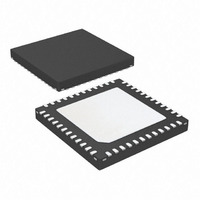
AT83C26-ZTUL Atmel, AT83C26-ZTUL Datasheet - Page 23

AT83C26-ZTUL
Manufacturer Part Number
AT83C26-ZTUL
Description
IC SMART CARD READER 1/PM 48-QFN
Manufacturer
Atmel
Datasheet
1.AT83C26-ALTUL.pdf
(77 pages)
Specifications of AT83C26-ZTUL
Controller Type
Smart Card Reader Interface
Interface
2-Wire
Voltage - Supply
3 V ~ 5.5 V
Current - Supply
65mA
Operating Temperature
-40°C ~ 85°C
Mounting Type
Surface Mount
Package / Case
48-VQFN Exposed Pad, 48-HVQFN, 48-SQFN, 48-DHVQFN
For Use With
AT89STK-09 - EVAL BOARD FOR AT83C26
Lead Free Status / RoHS Status
Lead free / RoHS Compliant
- Current page: 23 of 77
- Download datasheet (706Kb)
LDO initialization
Procedure
7511D–SCR–02/07
When the DC/DC B voltage rises the selected voltage (VDCB_OK=1), the card voltage selection
on CVCC2, CVCC3, CVCC4 or CVCC5 starts the corresponding LDO.
The CVCC2 card voltage must be started in first (if needed). When the VCARD_OK2 is set, the
CVCC3,CVCC4, CVCC5 card voltage are started one after each other (if needed) with the same
procedure.
The LDO2, LDO3, LDO4 and LDO5 share the DC/DCB output current, for example 75mA max
when CVCCB is pregrammed to 5V. (see Table 62.)
The SC2_FULL bit must be set to use SC2 full interface:
As the power supply of CIO3/CC42 and of CRST3/CC82 is CVCC3, when SC2_FULL=1,
CVCC3 = CVCC2. The SC3 interface is disable and LDO3 receives LDO2 command
(VCARD3[1:0] = VCARD2[1:0]).
Figure 11. LDOn Initialization Procedure (n = 2, 3, 4, 5)
The LDOn output voltage must be at 0V before to program 1.8V/3V/5V.
CIO3/CC42 is CC42 and CRST3/CC82 is CC82.
IPLUSn = 1
write VCARDn[1:0]
LDOn initialization
VCARD_OKn = 1
Time-out Expired
(VDCB_OK = 1)
DCDCB started
Set Timer 2ms
and IPLUSn=1
Init condition:
Start LDOn,
failure
?
LDOn started
AT83C26
23
Related parts for AT83C26-ZTUL
Image
Part Number
Description
Manufacturer
Datasheet
Request
R

Part Number:
Description:
SMART CARD READER INTERFACE WITH POWER MANAGEMENT
Manufacturer:
ATMEL [ATMEL Corporation]
Datasheet:

Part Number:
Description:
IC SMART CARD READER 1/PM 48VQFP
Manufacturer:
Atmel
Datasheet:

Part Number:
Description:
IC SMART CARD READER 1/PM 48VQFP
Manufacturer:
Atmel
Datasheet:

Part Number:
Description:
IC SMART CARD READER 3/5V 48VQFP
Manufacturer:
Atmel
Datasheet:

Part Number:
Description:
IC SMART CARD READER 1/PM 48-MLF
Manufacturer:
Atmel
Datasheet:

Part Number:
Description:
RFID Modules & Development Tools 3V Smart card reader
Manufacturer:
Atmel
Datasheet:

Part Number:
Description:
Multiple Smart Card Reader Interface With Power Management
Manufacturer:
ATMEL Corporation
Datasheet:

Part Number:
Description:
DEV KIT FOR AVR/AVR32
Manufacturer:
Atmel
Datasheet:

Part Number:
Description:
INTERVAL AND WIPE/WASH WIPER CONTROL IC WITH DELAY
Manufacturer:
ATMEL Corporation
Datasheet:

Part Number:
Description:
Low-Voltage Voice-Switched IC for Hands-Free Operation
Manufacturer:
ATMEL Corporation
Datasheet:

Part Number:
Description:
MONOLITHIC INTEGRATED FEATUREPHONE CIRCUIT
Manufacturer:
ATMEL Corporation
Datasheet:

Part Number:
Description:
AM-FM Receiver IC U4255BM-M
Manufacturer:
ATMEL Corporation
Datasheet:

Part Number:
Description:
Monolithic Integrated Feature Phone Circuit
Manufacturer:
ATMEL Corporation
Datasheet:

Part Number:
Description:
Multistandard Video-IF and Quasi Parallel Sound Processing
Manufacturer:
ATMEL Corporation
Datasheet:


