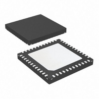
AT83C26-ZTUL Atmel, AT83C26-ZTUL Datasheet - Page 24

AT83C26-ZTUL
Manufacturer Part Number
AT83C26-ZTUL
Description
IC SMART CARD READER 1/PM 48-QFN
Manufacturer
Atmel
Datasheet
1.AT83C26-ALTUL.pdf
(77 pages)
Specifications of AT83C26-ZTUL
Controller Type
Smart Card Reader Interface
Interface
2-Wire
Voltage - Supply
3 V ~ 5.5 V
Current - Supply
65mA
Operating Temperature
-40°C ~ 85°C
Mounting Type
Surface Mount
Package / Case
48-VQFN Exposed Pad, 48-HVQFN, 48-SQFN, 48-DHVQFN
For Use With
AT89STK-09 - EVAL BOARD FOR AT83C26
Lead Free Status / RoHS Status
Lead free / RoHS Compliant
Activation Sequence Overview (n=1, 2, 3, 4, 5)
Software Activation for SCn interfaces (n=1, 2, 3, 4, 5) with ARTn bit = 0
24
AT83C26
The activation sequence on SC1 is only available if a card is detected on CPRES1 (CARDIN1 bit
= 1).
The activation sequence on SC2 is only available if a card is detected on CPRES2 (CARDIN2 bit
= 1).
The activation sequence on SC3, SC4, SC5, is only available if DC/DC B is started (VDCB_OK
= 1).
The SCn interface starts the activation sequence after a TWI write command in VCARDn[1:0]
bits to program the CVCCn voltage.
The SC3, SC4, SC5 interfaces (SIM/SAM interfaces) don’t have card presence detector.
After the DC/DC start, the user application will check the ATR to detect if a SIM/SAM is present
in the connector.
The automatic reset transition mode (ART=1) controls the CRST pin and check if the first start
bit of the ATR respects ISO7816 timings.
All status bits of an interface (see bits in registers with ”This bit is cleared by hardware when this
register is read”) must be cleared before to start an activation sequence.
The activation sequence is controlled by software using TWI commands, depending on the
cards to support. For ISO 7816 cards, the following sequence can be applied:
1. Card Voltage is set by software to the required value (VCARDn[1:0] bits). The TWI
2. Wait of the end of the DC/DC (or LDO) init with a polling on VCARD_OKn bit or wait
3. CKSTOPn, IODISn are programmed by software. CKSTOPn bit is reset to have the
4. CRSTn pin is controlled by software using CARDRSTn bit.
writing command in VCARDn[1:0] starts the DC/DC (or LDO).
for INT to go Low. When VCARD_OKn bit is set (by hardware), CARDIOn bit should
be set by software.
clock running. IODISn (see IO_SELECT for SC2, SC3, SC4, SC5) is reset to enable
the transparent mode on CIOn,CC4n, CC8n.
7511D–SCR–02/07


