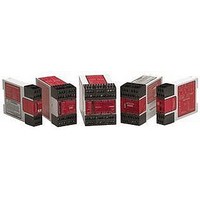
ES-TN-1H5 BANNER ENGINEERING, ES-TN-1H5 Datasheet

ES-TN-1H5
Specifications of ES-TN-1H5
Related parts for ES-TN-1H5
ES-TN-1H5 Summary of contents
Page 1
... Printed in USA E-Stop Safety Modules with Adjustable Delay Models ES-TN-1H5 with 0-20 second delay, ES-TN-1H6 with 0-200 second delay Features • Selectable Auto-Reset or monitored Manual Reset. • Auto or manual power-up • One- or two-channel feedback monitoring • ...
Page 2
... Also, request a type “C” standard for your specific machinery. “Safety of Machinery – Emergency Stop Equipment Functional Aspects, Principles for Design” Available from: Global Engineering Documents 15 Inverness Way East Englewood, CO 80112-5704 Tel.: 800-854-7179 — Models ES-TN-1H5/-1H6 Banner Engineering Corp. Minneapolis, MN U.S.A. • www.bannerengineering.com • Tel: 763.544.3164 ...
Page 3
... DC-injection brakes or reverse current via the machine’s actuators are commonly used. The outputs of E-stop Safety Modules ES-TN-1H5 and -1H6 are two redundant normally open immediate safety contacts (each of which is a series of two forced- guided relay contacts, K1 and K2 in Figure 2), and two redundant normally open delayed contacts (also each a series of two forced-guided relay contacts, K3 and K4) ...
Page 4
... NFPA 79 standards require that a Reset routine be performed after returning the E-stop switch to its closed-contact position. This prevents the controlled machinery from restarting simply by closing the E-stop switch. Models ES-TN-1H5 and -1H6 may be configured for Automatic Reset via two DIP switches located inside the Module housing, under the front cover (see Figures 5 and 6) ...
Page 5
... E-stop contacts opens. The second contact, however, must open within 2 seconds of the first one; if not, the unit will go into a lockout condition that results in the outputs opening and requiring a reset after the fault has been corrected. — Models ES-TN-1H5/-1H6 P/N 58697 rev ...
Page 6
... Safety Module which interfaces to a multitude of machine control configurations. The following guidelines are general in nature. Models ES-TN-1H5 and -1H6 have two redundant immediate normally open supply output contacts (13-14 and 23-24), as well as two redundant delayed contacts (37-38 and 47-48). This qualifies this E-Stop Module to be used in applications as a functional stop Category E-Stop Control as defined by NFPA 79 and ISO 13850 (EN 418) ...
Page 7
... Reset mode) or re-arming the E-stop button (Auto Reset mode) before the time-out occurs will result in a lockout (see page 14 for instructions for clearing lockouts). *** Arc suppressors (see WARNING). Figure 3. E-Stop Safety Modules ES-TN-1H5 and -1H6 hookups — Models ES-TN-1H5/-1H6 dc common 24V dc ...
Page 8
... E-Stop Safety Modules with Adjustable Delay Connection of Safety Switches Models ES-TN-1H5 and ES-TN-1H6 may be used as a safety gate monitoring module. To achieve Safety Category 4 operation per EN954-1, two individually mounted, positive-opening safety switches that operate concurrently when the gate or guard is opened must be used (see Figure 4). ...
Page 9
... Reset button is pushed and released. If Manual Power-Up and Auto Reset is selected, the E-stop button must be cycled (opened and closed closed after power up (but simply closed open after power-up). — Models ES-TN-1H5/-1H6 P/N 58697 rev ...
Page 10
... X3-X4 and X5-X6 inputs and select 2-channel monitoring the responsibility of the user to ensure that any single failure will not result in a hazardous condition and will prevent a successive machine cycle. 10 P/N 58697 rev. A — Models ES-TN-1H5/-1H6 CAUTION . . . ! Turn OFF Power Before Removing Cover ...
Page 11
... The installation, including its wiring, must be designed to prevent any hazard which could result from the loss of a programmed output switching delay time. — Models ES-TN-1H5/-1H6 Factory Setting Optional Setting 1 – Auto reset 1 – 2-Channel Monitoring 1 – Auto power-up 1 – ...
Page 12
... Safety Module front cover. Then insert the blade of a small screwdriver into one of the four depressions in the Safety Module front cover and pry them loose; see Figure 7. 12 P/N 58697 rev. A 1-channel E-stop: S21-S22 Auto reset: X1-X2 — Models ES-TN-1H5/-1H6 Front Cover Plate ...
Page 13
... Always disconnect power to the machine control elements before opening the enclosure housing of the E-stop Safety Module. E-Stop Safety Modules ES-TN-1H5 and -1H6 provide seven indicator LEDs Power ON – Power is connected to terminals A1-A2 (green) OFF – No power or low power to terminals A1-A2, or internal power supply failure Fault ON – ...
Page 14
... In Auto Reset mode, the E-Stop button was re-armed (closed) with cancel delay input closed Manual Reset mode, the E-Stop button was re-armed (closed) and the reset button pushed and released with cancel delay input closed. — Models ES-TN-1H5/-1H6 Banner Engineering Corp. Minneapolis, MN U.S.A. ...
Page 15
... NOTE: Transient suppression is recommended when switching inductive loads. Install suppressors Output Response Time K1 & K2: 50 milliseconds typical K3 & K4 (ES-TN-1H5 10, 15, 20 seconds K3 & K4 (ES-TN-1H6 10, 20, 30, 50, 70, 100, 150, 200 seconds Delayed Output Timing Tolerance: Set time ±100 ms or ±2%, whichever is greater Input Requirements E-stop switch must have normally closed contact capable of switching 24V dc ...
Page 16
... Figure 8. E-Stop Safety Modules ES-TN-1H5 and ES-TN-1H6 enclosure dimensions NOTE: Do not attempt any repairs to the ES-TN-1H5 or 1H6 Emergency Stop Safety Module. It contains no field-replaceable components. Return the Safety Module to the factory for warranty repair or replacement ever becomes necessary to return an E-Stop Safety Module to the factory, please ...


