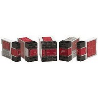
ES-TN-1H5 BANNER ENGINEERING, ES-TN-1H5 Datasheet - Page 7

ES-TN-1H5
Manufacturer Part Number
ES-TN-1H5
Description
MODULE; SAFETY; E-STOP GUARD; MONITORING MODULE
Manufacturer
BANNER ENGINEERING
Datasheet
1.ES-TN-1H5.pdf
(16 pages)
Specifications of ES-TN-1H5
Coil Voltage Vdc Nom
24V
Contact Current Max
4A
Contact Voltage Ac Nom
250V
Contact Voltage Dc Nom
250V
Contact Configuration
SPST-NC
No. Of Poles
1
Relay Mounting
DIN Rail
External Height
85.5mm
installed as shown across the
actuator coil of the Master Stop
Control elements (MSC1 to MSC4).
NEVER install suppressors directly
across the output contacts of
the E-Stop Safety Module. It is
possible for suppressors to fail as
a short circuit. If installed directly
across the output contacts of the
Safety Module, a short-circuited
suppressor will create an unsafe
condition which could result in
serious injury or death.
PLC, PES, PC) between E-Stop Safety
Module outputs and the Master Stop
Control Element it switches, in such a
manner that:
• In the event of a failure there is a loss
• The safety function can be
Whenever forced-guided, mechanically
linked relays are added as intermediate
switching devices, a normally closed
forced-guided monitor contact from
each relay must be added to the
series feedback loop between Safety
Module terminals X3 and X4 or X5
and X6.
Banner Engineering Corp.
of the safety stop command, or,
suspended, overridden, or defeated,
unless accomplished with the same
or greater degree of safety.
www.bannerengineering.com • Tel: 763.544.3164
!
!
E-Stop Safety Modules with Adjustable Delay
WARNING . . .
Wiring of Arc Suppressors
If arc suppressors are
used, they MUST be
WARNING . . .
Interfacing MSCs
NEVER wire an
intermediate device (e.g.,
•
Minneapolis, MN U.S.A.
Figure 3. E-Stop Safety Modules ES-TN-1H5 and -1H6 hookups
(See WARNING)
for 1-channel
*(Jumper on
Emergency Stop Switch
Cancel Delay Input
S21-S22
E-Stop)
L1
*** Arc suppressors (see WARNING).
** The Safety Module can not be reset until the delay output times out and
* See page 10 for DIP-switch configuration.
Non-safety Auxiliary
Machine
switches, or until the Cancel Delay Input is exercised. Attempting to reset
the module (Manual Reset mode) or re-arming the E-stop button (Auto
Reset mode) before the time-out occurs will result in a lockout (see page
14 for instructions for clearing lockouts).
Monitor Contacts
Circuits
Control
+V
S22
S11
S21
S12
A1
Y1
Y2
13
23
37
47
51
61
ES-TN-1H5
ES-TN-1H6
K1
Immediate
K1
Immediate
K3
K3
Immediate
Delayed
Delayed
K1
Delayed
K2
K3
K4
A
B
A
B
24V dc
4A max.
4A max.
4A max.
4A max.
C
C
C
C
K2
K2
K4
K4
A
B
A
B
— Models ES-TN-1H5/-1H6
A2
14
24
38
48
62
X1
X2
X3
X4
X5
X6
52
Machine Master
MSC1
MSC3
MSC2
MSC4
dc common
Stop Control
Elements
MSC1
***
***
MSC3
***
MSC4
***
MSC2
Reset
Switch**
(jumper for Auto Reset -
see ?Warning on page 9)*
MSC-Monitor Contacts
(jumper if no feedback
contacts are monitored)*
MSC-Monitor Contacts
(jumper if 1 channel feedback
is selected or no feedback)*
L2
P/N 58697 rev. A
7


