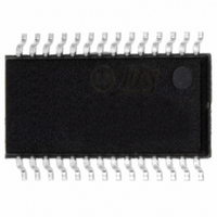
ST7540TR STMicroelectronics, ST7540TR Datasheet - Page 25

ST7540TR
Manufacturer Part Number
ST7540TR
Description
IC TXRX FSK POWER LINE 28-TSSOP
Manufacturer
STMicroelectronics
Type
Transceiverr
Datasheet
1.ST7540TR.pdf
(44 pages)
Specifications of ST7540TR
Number Of Drivers/receivers
1/1
Voltage - Supply
5 V ~ 9 V
Mounting Type
Surface Mount
Package / Case
28-TSSOP Exposed Pad, 28-eTSSOP, 28-HTSSOP
For Use With
497-5485 - BOARD EVAL ST7540 PWR LINE TXRX
Lead Free Status / RoHS Status
Lead free / RoHS Compliant
Protocol
-
Lead Free Status / Rohs Status
Compliant
Other names
497-5528-2
Available stocks
Company
Part Number
Manufacturer
Quantity
Price
Company:
Part Number:
ST7540TR
Manufacturer:
FENGHUA
Quantity:
400 000
Company:
Part Number:
ST7540TR
Manufacturer:
ST
Quantity:
2 100
Part Number:
ST7540TR
Manufacturer:
ST
Quantity:
20 000
ST7540
●
●
●
Carrier Detection
The Carrier/Preamble detection Block notifies to the host controller the presence of a
Carrier when it detects on the RX_IN Input a signal with an harmonic component close
to the programmed Carrier Frequency. The CD_PD signal sensitivity is identical to the
data reception sensitivity (0.5mVrms Typ. in Normal Sensitivity Mode). When the
device sensitivity is set by the TxD line (Sensitivity level equal to BU threshold) the
CD_PD signal is conditioned to the BU signal.
The CD_PD line is forced to a logic level low when a Carrier is detected.
Preamble Detection
The Carrier/Preamble detection Block notifies to the host controller the presence of a
Carrier modulated at the Programmed Baud Rate for at least 4 Consecutive Symbols
(“1010” or “0101” are the symbols sequences detected).
CD_PD line is forced low till a Carrier signal is detected and PLL is in the lock-in range.
To reinforce the effectiveness of the information given by CD_PD Block, a digital
filtering is applied on Carrier or Preamble notification signal (see
register). The Detection Time Bits in the Control Register define the filter performance.
Increasing the Detection Time reduced the false notifications caused by noise on main
line. The Digital filter adds a delay to CD_PD notification equal to the programmed
Detection Time. When the carrier frequency disappears, CD_PD line is held low for a
period equal to the detection time and then forced high. During this time, some
spurious data caused by noise can be demodulated and sent over RxD line.
Header Recognition
In Control Register Extended Mode (Control Register bit 21=”1”, see
CD_PD line can be used to recognize if an header has been sent during the
transmission. With Header Recognition function enable (Control Register bit 18=”1”,
see
Length Count function is enabled, CD_PD is held low and a number of 16 bit word
equal to the Frame Length selected is sent to the host controller. In this case, CLR/T is
forced to “0” and RxD is forced to “0” or “1” (according the UART/SPI pin level) when
Header has not been detected or after the Frame Length has been reached.
If Frame Length Count function is disabled, an header recognition is signaled by forcing
CD_PD low for one period of CLR/T line. In this case, CLR/T and RxD signal are
always present, even if no header has been recognized.
Table
12), CD_PD line is forced low when a Frame Header is detected. If Frame
Functional description
Section 6.8: Control
Table
12) the
25/44


