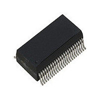
ICS1893BF IDT, Integrated Device Technology Inc, ICS1893BF Datasheet - Page 13

ICS1893BF
Manufacturer Part Number
ICS1893BF
Description
PHYCEIVER LOW PWR 3.3V 48-SSOP
Manufacturer
IDT, Integrated Device Technology Inc
Series
PHYceiver™r
Type
PHY Transceiverr
Specifications of ICS1893BF
Protocol
MII
Voltage - Supply
3.14 V ~ 3.47 V
Mounting Type
Surface Mount
Package / Case
48-SSOP
Lead Free Status / RoHS Status
Contains lead / RoHS non-compliant
Number Of Drivers/receivers
-
Lead Free Status / Rohs Status
Not Compliant
Other names
1893BF
Available stocks
Company
Part Number
Manufacturer
Quantity
Price
Part Number:
ICS1893BF
Manufacturer:
ICS
Quantity:
20 000
Company:
Part Number:
ICS1893BFI
Manufacturer:
OKI
Quantity:
1 934
Part Number:
ICS1893BFILF
Manufacturer:
ICS
Quantity:
20 000
Company:
Part Number:
ICS1893BFLF
Manufacturer:
ICS
Quantity:
409
Part Number:
ICS1893BFLF
Manufacturer:
ICS
Quantity:
20 000
Part Number:
ICS1893BFLFT
Manufacturer:
IDT
Quantity:
20 000
ICS1893BF, Rev. F, 5/13/10
Table 2-1. Conventions and Nomenclature (Continued)
Signal references
Symbols
Terms:
‘set’,
‘active’,
‘asserted’,
Terms:
‘cleared’,
‘de-asserted’,
‘inactive’
Terms:
‘twisted-pair receiver’
Terms:
‘twisted-pair transmitter’
ICS1893BF Data Sheet Rev. F - Release
Item
The terms ‘set’, ‘active’, and ‘asserted’ are synonymous.
They do not necessarily infer logic one.
(For example, an active-low signal can be set to logic zero.)
The terms ‘cleared’, ‘inactive’, and ‘de-asserted’ are synonymous.
They do not necessarily infer logic zero.
In reference to the ICS1893BF, the term ‘Twisted-Pair Receiver’ refers to the
set of Twisted-Pair Receive output pins (TP_RXP and TP_RXN).
In reference to the ICS1893BF, the term ‘Twisted-Pair Transmitter’ refers to
the set of Twisted-Pair Transmit output pins (TP_TXP and TP_TXN).
•
•
•
•
When referring to signals, the terms:
– ‘FALSE’, ‘low’, or ‘zero’ represent signals that are logic zero.
– ‘TRUE’, ‘high’, or ‘one’ represent signals that are logic one.
Chapter 9, “DC and AC Operating Conditions”
specifications for ‘logic zero’ and ‘logic one’ signals.
In this data sheet, code group names are referred to as ‘symbols’ and they
are shown between '/' (slashes). For example, the symbol /J/ represents
the first half of the Start-of-Stream Delimiter (SSD1).
Symbol sequences are shown in succession. For example, /I/J/K/
represents an IDLE followed by the SSD.
Copyright © 2009, IDT, Inc.
All rights reserved.
13
Convention / Nomenclature
Chapter 2 Conventions and Nomenclature
defines the electrical
May, 2010


