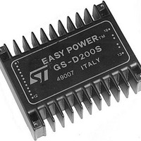
GS-D200 STMicroelectronics, GS-D200 Datasheet

GS-D200
Specifications of GS-D200
Available stocks
Related parts for GS-D200
GS-D200 Summary of contents
Page 1
... The GS-D200 uses bipolar power outputs while the GS-D200S has powermos outputs to significantly reduce both commutation and conduction losses. A further benefit offered by the GS-D200S is the complete protection of the outputs against any type of shorts. SELECTION CHART Type ...
Page 2
... T cop ELECTRICAL CHARACTERISTICS (T Symbol Parameter Quiescent Supply Current I s Quiescent Logic Supply Current I ss Input Voltage V i Input Current I i Source/Sink Saturation Voltage(GS-D200) V sat Source/Sink Saturation Voltage(GS-D200S) V sat Current Limit Intervention I oL Chopper Frequency f c Stepckl Width t clk Set Up Time t s Hold Time ...
Page 3
... Figure 2: GS-D200 and GS-D200S Block Diagram GS-D200/GS-D200S 3/17 ...
Page 4
... GS-D200/GS-D200S Figure 3: GS-D Modules Typical Application Figure 4: GS-D200 and GS-D200S Connection Diagram (Top view) 4/17 ...
Page 5
... The oscillator input must be grounded when the unit is externally synchronized. Phase current setting input. A resistor connected between this pin and Gnd1 oset allows the factory setted phase current value (1A for GS-D200 and 2A for GS-D200S changed. Logic input that allows the phase current decay mode selection. When high or ...
Page 6
... GS-D200/GS-D200S BIPOLAR STEPPER MOTOR BASICS Simplified to the bare essentials, a bipolar perma- nent magnet motor consists of a rotating-perma- nent magnet surrounded by stator poles carrying the windings (fig. 5). Figure 5: Simplified Bipolar Two Phase Motor Bidirectional drive current is imposed on windings A-B and C-D and the motor is stepped by commu- tating the voltage applied to the windings in se- quence ...
Page 7
... Figure 7: Two-Phase-on (Normal Mode) Drive Figure 8: Half Step Sequence GS-D200/GS-D200S 7/17 ...
Page 8
... GS-D200/GS-D200S PHASE SEQUENCE GENERATION INSIDE THE GS-D200/GS-D200S The modules contains a three bit counter plus some combinational logic which generate suitable phase sequences for half step, wave and normal full step drive. This 3 bit counter generates a basic eight-step Gray code master sequence as shown in fig ...
Page 9
... D200, the voltages on A and B are shown as well as the current waveform on winding AB. When the CONTROL input is forced low, the decay is fast as shown in fig. 13. The CONTROL input is provided on GS-D200 and GS-D200S to allow maximum flexibility in applica- tion. If the modules must drive a large motor that does ...
Page 10
... GS-D200/GS-D200S Figure 12: Chopper Control with Slow Decay Figure 13: Chopper Control with Fast Decay 10/17 drive current ( ON – – – – recirculation current (Q ON, Q OFF drive current ( ON – – – – recirculation current ( OFF ON ...
Page 11
... All the GS-D200 and GS-D200S logic inputs have an internal pull-up, and they are high when uncon- nected. Phase Current Programming The output current of the GS-D200 is factory set to 1A while the GS-D200S has a standard 2A value. The phase current value can be changed by con- necting an appropriate resistor between pin 9 and ground or V (see fig ...
Page 12
... GS-D200/GS-D200S Figure 14: GS-D200 and GS-D200S Phase Current Programming Chopper Frequency Programming The chopper frequency is internally set to 17kHz, and it can be changed by addition of external components as follows. To increase the chopper frequency a resistor must be connected between Oscillator (pin 8) and V (pin 12, see fig. 15). ss The resistor value is calculated according to the ...
Page 13
... If all the motors are relatively small, the fast decay may be used, the chopper frequency does not need Figure 18: Multimotor Synchronization. Small Motor and Fast Current Decay Figure 17: GS-D200S Free Air Derating Curve Tamb ( C) any adjustement and fig. 18 shows how to synchro- nize several modules. ...
Page 14
... C during op- output stage to obtain the average voltage (this D.C. is automatically adjusted by the GS-D200): V D.C. Calculate the power dissipation of the GS-D200 output power stage. The power dissipation de- pends on two main factors: – the selected operating mode (FAST or SLOW DECAY) – the selected drive sequence (WAVE, NORMAL, HALF STEP) FAST DECAY ...
Page 15
... In stall condition the worst case for power dissipation is with two-phase-on i.e. a power dissipation as in NORMAL MODE. The following table summarizes the power dissipa- tions of the output power stage of the GS-D200 when running for this example: Wave Normal Fast Decay 3 ...
Page 16
... GS-D200/GS-D200S MECHANICAL DATA 2.2 (0.87) 2.54 (0.1) 29.5 18.4 (1.16) (0.72) 23.0 (0.90) 2.2 (0.87) Dimensions in mm MOTHER BOARD LAYOUT 16/17 85.5 (3.37) 5.04 (0.2) 5.04 (0.2) 5.04 (0.2) 1.2 (0.47) 66.67 (2.62) 78.5 (3.09) 82.3 (3.24) 0.5 (0.02) 20.5 (0.81) 18 ...
Page 17
... SGS-THOMSON Microelectronics. © 1994 SGS-THOMSON Microelectronics – All Rights Reserved SGS-THOMSON Microelectronics GROUP OF COMPANIES Australia - Brazil - China - France - Germany - Hong Kong - Italy - Japan - Korea - Malaysia - Malta - Morocco - The Netherlands - Singapore - Spain - Sweden - Switzerland - Taiwan - Thailand - United Kingdom - U.S.A. GS-D200/GS-D200S 17/17 ...


