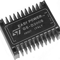
GS-D200 STMicroelectronics, GS-D200 Datasheet - Page 6

GS-D200
Manufacturer Part Number
GS-D200
Description
Motor / Motion / Ignition Controllers & Drivers 2/2.5A Stepper
Manufacturer
STMicroelectronics
Type
Stepper Motor Controllerr
Datasheet
1.GS-D200S.pdf
(17 pages)
Specifications of GS-D200
Product
Stepper Motor Controllers / Drivers
Operating Supply Voltage
40 V
Mounting Style
SMD/SMT
Package / Case
Module
Lead Free Status / Rohs Status
Lead free / RoHS Compliant
Available stocks
Company
Part Number
Manufacturer
Quantity
Price
Company:
Part Number:
GS-D200S
Manufacturer:
ST
Quantity:
5 510
Figure 5: Simplified Bipolar Two Phase Motor
Figure 6: One-Phase-on (Wave Mode) Drive
GS-D200/GS-D200S
BIPOLAR STEPPER MOTOR BASICS
Simplified to the bare essentials, a bipolar perma-
nent magnet motor consists of a rotating-perma-
nent magnet surrounded by stator poles carrying
the windings (fig. 5).
Bidirectional drive current is imposed on windings
A-B and C-D and the motor is stepped by commu-
tating the voltage applied to the windings in se-
quence. For a motor of this type there are three
possible drive sequences.
6/17
One-Phase-on or Wave Drive
Only one winding is energized at any given time
according to the sequence :
(BA means that the current is flowing from B to A).
Fig. 6 shows the sequence for a clockwise rotation
and the corresponding rotor position.
Two-Phase-on or Normal Drive
This mode gives the highest torque since two wind-
ings are energized at any given time according to
the sequence (for clockwise rotation).
AB & CD ; CD & BA ; BA & DC ; DC & AB
Fig. 7 shows the sequence and the corresponding
position of the rotor.
Half Step Drive
This sequence halves the effective step angle of
the motor but gives a less regular torque being one
winding or two windings alternatively energized.
Eight steps are required for a complete revolution
of the rotor.
The sequence is:
as shown in fig. 8.
By the configurations of fig. 6, 7, 8 the motor would
have a step angle of 90 (or 45 in half step). Real
motors have multiple poles pairs to reduce the step
angle to a few degrees but the number of windings
(two) and the drive sequence are unchanged.
AB ; AB & CD ; CD ; CD & BA ; BA ; BA & DC ;
AB - CD - BA - DC
DC ; DC & AB


