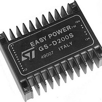
GS-D200 STMicroelectronics, GS-D200 Datasheet - Page 5

GS-D200
Manufacturer Part Number
GS-D200
Description
Motor / Motion / Ignition Controllers & Drivers 2/2.5A Stepper
Manufacturer
STMicroelectronics
Type
Stepper Motor Controllerr
Datasheet
1.GS-D200S.pdf
(17 pages)
Specifications of GS-D200
Product
Stepper Motor Controllers / Drivers
Operating Supply Voltage
40 V
Mounting Style
SMD/SMT
Package / Case
Module
Lead Free Status / Rohs Status
Lead free / RoHS Compliant
Available stocks
Company
Part Number
Manufacturer
Quantity
Price
Company:
Part Number:
GS-D200S
Manufacturer:
ST
Quantity:
5 510
PIN DESCRIPTION
Pin
10
12
13
14
15
16
17
18
11
1
2
3
4
5
6
7
8
9
GND1
Sync
Reset
Half/Full
Home
Stepclk
CW/CCW
Oscillator
I oset
Control
Enable
V ss
GND2
D
C
B
A
V s
Function
Return path for the logic signals and 5V supply.
Chopper oscillator output.
Several modules can be synchronized by connecting together all Sync pins. This pin can
be used as the input for an external clock source.
Asynchronous reset input. An active low pulse on this input preset the internal logic to the
initial state (ABCD=0101).
Half/Full step selection input.
When high or unconnected the half step operation is selected.
When high, this output indicates that the internal counter is in its initial state (ABCD=0101).
This signal may be used in conjunction with a mechanical switch to ground or with open
collector output of an optical detector to be used as a system home detector.
The motor is moved one step on the rising edge of this signal.
Direction control input. When high or unconnected clockwise rotation is selected. Physical
direction of motor rotation depends also on windings connection.
The chopper oscillator timing, internally fixed at 17kHz, can be modified by connecting a
resistor between this pin and V ss or a capacitor between this pin and Gnd1.
The oscillator input must be grounded when the unit is externally synchronized.
Phase current setting input. A resistor connected between this pin and Gnd1 or V ss ,
allows the factory setted phase current value (1A for GS-D200 and 2A for GS-D200S) to
be changed.
Logic input that allows the phase current decay mode selection. When high or
unconnected the slow decay is selected.
Module enable input. When low this input floats the outputs enabling the manual
positioning of the motor. Must be LOW during power-up and down sequence, HIGH during
normal operation.
5V supply input. Maximum voltage must not exceed 7V.
Return path for the power section.
D output.
C output.
B output.
A output.
Module and motor supply voltage.
Maximum voltage must not exceed the specified values.
Description
GS-D200/GS-D200S
5/17


