HD3-6408-9Z Intersil, HD3-6408-9Z Datasheet - Page 5
HD3-6408-9Z
Manufacturer Part Number
HD3-6408-9Z
Description
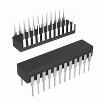
IC ASMA ADT CMOS 1.25MHZ 24DIP
Manufacturer
Intersil
Type
Manchester Encoder/Decoderr
Datasheet
1.HD3-6408-9Z.pdf
(11 pages)
Specifications of HD3-6408-9Z
Applications
Security Systems
Voltage - Supply, Analog
4.5 V ~ 5.5 V
Voltage - Supply, Digital
4.5 V ~ 5.5 V
Mounting Type
Through Hole
Package / Case
24-DIP (0.600", 15.24mm)
Lead Free Status / RoHS Status
Lead free / RoHS Compliant
Available stocks
Company
Part Number
Manufacturer
Quantity
Price
Company:

Part Number:
HD3-6408-9Z
Manufacturer:
Intersil
Quantity:
30


Decoder Operation
The Decoder requires a single clock with a frequency of 12
times the desired data rate applied at the DClock input. The
Manchester II coded data can be presented to the Decoder
in one of two ways. The BOI and BZI inputs will accept data
from a differential output comparator. The UDI input can only
accept noninverted Manchester II coded data (e.g. from
BOO of an Encoder through an inverter to UDI).
The Decoder is free running and continuously monitors its
data input lines for a valid sync character and two valid
Manchester data bits to start an output cycle. When a valid
sync is recognized (1), the type of sync is indicated by the
CDS output. If the sync character was a command, this
output will go high (2) and remain high for sixteen DSC
periods (3), otherwise it will remain low. The TD output will
go high and remain high (2) - (3) while the Decoder is
transmitting the decoded data through SDO.
TIMING
SDO
DSC
CDS
BOI
BZI
VW
TD
FROM PREVIOUS RECEPTION
1ST HALF
SYNC
0
UNDEFINED
1
5
2ND HALF
SYNC
2
15
15
3
4
14
14
1
2
5
13
13
15
12
12
6
HD-6408
14
11
11
7
13
The decoded data available at SDO is in a NRZ format. The
DSC is provided so that the decoded bits can be shifted into
an external register on every low-to-high transition of this
clock (2) - (3). Note that DECODER SHIFT CLOCK may
adjust its phase up until the time that TAKE DATA goes high.
After all sixteen decoded bits have been transmitted (3) the
data is checked for odd parity. A high on VW output (4)
indicates a successful reception of a word without any
Manchester or parity errors. At this time the Decoder is
looking for a new sync character to start another output
sequence. VALID WORD will go low approximately 20
DECODER SHIFT CLOCK periods after it goes high if not
reset low sooner by a valid sync and two valid Manchester
bits as shown (1).
At any time in the above sequence a high input on DR during
a low-to-high transition of DSC will abort transmission and
initialize the Decoder to start looking for a new sync character.
10
10
8
12
16
2
2
4
17
1
1
3
18
0
0
2
19
P
P
1
0
3
4
March 7, 2006
FN2952.2
Related parts for HD3-6408-9Z
Image
Part Number
Description
Manufacturer
Datasheet
Request
R

Part Number:
Description:
IC BIT RATE GEN CMOS 16-PDIP
Manufacturer:
Intersil
Datasheet:

Part Number:
Description:
IC ENCODER-DECODER CMOS 20-PDIP
Manufacturer:
Intersil
Datasheet:

Part Number:
Description:
IC UART CMOS 5V 2MHZ 40-DIP
Manufacturer:
Intersil
Datasheet:

Part Number:
Description:
CMOS; 16 Lead PDIP; 2.4576 M Hz; CMOS; 16 per Bit Hz; On-Chip Input Pull-Up; 16
Manufacturer:
Intersil
Datasheet:
Part Number:
Description:
Encoder/Decoder; PDIP; On Chip; 5 V
Manufacturer:
Intersil
Datasheet:

Part Number:
Description:
06F5779
Manufacturer:
Intersil
Datasheet:

Part Number:
Description:
CMOS Manchester Encoder-decoder
Manufacturer:
Intersil Corporation
Datasheet:

Part Number:
Description:
CMOS Manchester Encoder-Decoder
Manufacturer:
INTERSIL [Intersil Corporation]
Datasheet:
Part Number:
Description:
Intersil Corporation [CMOS Serial Controller Interface]
Manufacturer:
Intersil Corporation
Datasheet:
Part Number:
Description:
Manufacturer:
Intersil Corporation
Datasheet:
Part Number:
Description:
357-036-542-201 CARDEDGE 36POS DL .156 BLK LOPRO
Manufacturer:
Intersil Corporation
Datasheet: