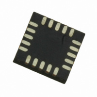
MPR121QR2 Freescale Semiconductor, MPR121QR2 Datasheet - Page 48

MPR121QR2
Manufacturer Part Number
MPR121QR2
Description
IC CTLR TOUCH SENSOR 20-QFN
Manufacturer
Freescale Semiconductor
Type
Capacitive, Proximity Sensorr
Datasheet
1.MPR121QR2.pdf
(57 pages)
Specifications of MPR121QR2
Number Of Inputs/keys
12 Key
Data Interface
I²C, Serial
Voltage - Supply
1.71 V ~ 3.6 V
Current - Supply
29µA
Operating Temperature
-40°C ~ 85°C
Mounting Type
Surface Mount
Package / Case
20-UQFN, 20-µQFN
Output Type
Logic
Interface
I²C
Input Type
Logic
Supply Voltage
2.5 V to 3.6 V
Dimensions
3 mm L x 3 mm W x 0.65 mm H
Temperature Range
- 40 C to + 85 C
Termination Style
SMD/SMT
Supply Current
29µA
Ic Interface Type
I2C
Supply Voltage Range
1.71V To 3.6V
Sensor Case Style
QFN
No. Of Pins
20
Operating Temperature Range
-40°C To +85°C
Interface Type
I2C
Rohs Compliant
Yes
Lead Free Status / RoHS Status
Lead free / RoHS Compliant
Other names
MPR121QR2
MPR121QR2TR
MPR121QR2TR
Available stocks
Company
Part Number
Manufacturer
Quantity
Price
Part Number:
MPR121QR2
Manufacturer:
FREESCALE
Quantity:
20 000
MPR121
48
BIT TRANSFER
One data bit is transferred during each clock pulse
ACKNOWLEDGE
The acknowledge bit is a clocked 9
each byte transferred effectively requires 9 bits. The master generates the 9
during the acknowledge clock pulse, such that the SDA line is stable low during the high period of the clock pulse. When the
master is transmitting to the MPR121, the MPR121 generates the acknowledge bit, since the MPR121 is the recipient. When the
MPR121 is transmitting to the master, the master generates the acknowledge bit, since the master is the recipient.
THE SLAVE ADDRESS
The MPR121 has a 7-bit long slave address
is low for a write command and high for a read command.
The MPR121 monitors the bus continuously, waiting for a START condition followed by its slave address. When a MPR121
recognizes its slave address, it acknowledges and is then ready for continued communication.
The MPR121 slave addresses are show in
BY TRANSMITTER
BY RECEIVER
SDA
SCL
SDA
SCL
SDA
SDA
SCL
CONDITION
START
CONDITION
MSB
S
START
1
S
th
bit
0
Table 46.
VDD
VSS
SDA
SCL
(Figure
ADDR Pin Connection
Table
(Figure
1
0
51) which the recipient uses to handshake receipt of each byte of data. Thus
46.
Figure 52. Slave Address
Figure 51. Acknowledge
(Figure
Figure 50. Bit Transfer
52). The bit following the 7-bit slave address (bit eight) is the R/W bit, which
1
50). The data on SDA must remain stable while SCL is high.
2
0
I
2
C Address
1
ACKNOWLEDGEMENT
0x4C
0x4D
0x4E
0x4F
th
clock pulse, and the recipient pulls down SDA
CLOCK PULSE FOR
0
8
R/W
CONDITION
ACK
Freescale Semiconductor
STOP
P
9
Sensors


