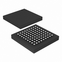
PX1011BI-EL1/G,551 NXP Semiconductors, PX1011BI-EL1/G,551 Datasheet - Page 14

PX1011BI-EL1/G,551
Manufacturer Part Number
PX1011BI-EL1/G,551
Description
IC PCI-EXPRESS X1 PHY 81-LFBGA
Manufacturer
NXP Semiconductors
Specifications of PX1011BI-EL1/G,551
Package / Case
81-LFBGA
Applications
PCI Express MAX to PCI Express PHY
Interface
JTAG
Voltage - Supply
1.2 V
Mounting Type
Surface Mount
Input Voltage Range (max)
0.31 V
Maximum Operating Temperature
+ 85 C
Maximum Power Dissipation
300 mW
Minimum Operating Temperature
- 40 C
Mounting Style
SMD/SMT
Operating Supply Voltage
1.2 V
Supply Current (max)
28 mA
Lead Free Status / RoHS Status
Lead free / RoHS Compliant
Lead Free Status / RoHS Status
Lead free / RoHS Compliant, Lead free / RoHS Compliant
Other names
935282114551
PX1011BI-EL1/G-S
PX1011BI-EL1/G-S
PX1011BI-EL1/G-S
PX1011BI-EL1/G-S
Available stocks
Company
Part Number
Manufacturer
Quantity
Price
Company:
Part Number:
PX1011BI-EL1/G,551
Manufacturer:
NXP Semiconductors
Quantity:
10 000
NXP Semiconductors
PX1011B_4
Product data sheet
8.9 Clock tolerance compensation
Table 14
Table 14.
The PHY receiver contains an elastic buffer used to compensate for differences in
frequencies between bit rates at the two ends of a link. The elastic buffer is capable of
holding at least seven symbols to handle worst case differences (600 ppm) in frequency
and worst case intervals between SKP ordered-sets. The PHY is responsible for inserting
or removing SKP symbols in the received data stream to avoid elastic buffer overflow or
underflow. The PHY monitors the receive data stream, and when a Skip ordered-set is
received, the PHY can add or remove one SKP symbol from each SKP ordered-set as
appropriate to manage its elastic buffer. Whenever a SKP symbol is added or removed,
the PHY will signal this to the MAC using the RXSTATUS signals. These signals have a
non-zero value for one clock cycle and indicate whether a SKP symbol was added or
removed from the received SKP ordered-set. RXSTATUS should be asserted during the
clock cycle when the COM symbol of the SKP ordered-set is moved across the parallel
interface. If the removal of a SKP symbol causes no SKP symbols to be transferred across
the parallel interface, then RXSTATUS is asserted at the same time that the COM symbol
(that was part of the received skip ordered-set) is transmitted across the parallel interface.
Figure 9
Figure 10
ordered-set.
PWRDWN[1:0]
P0: 00b
P0s: 01b
P1: 10b
Fig 9.
RXSTATUS2,
RXSTATUS1,
RXSTATUS0
RXDATA[7:0]
shows a sequence where the PHY inserted a SKP symbol in the data stream.
RXVALID
summarizes the function of some PXPIPE control signals.
Clock correction - insert a SKP
shows a sequence where the PHY removed a SKP symbol from a SKP
RXCLK
Control signals function summary
RXDET_LOOPB
0
0
1
1
X
X
0
1
active
000b
Rev. 04 — 4 September 2009
COM
001b
TXIDLE
0
1
0
1
0
1
0
1
1
000b
SKP
Function description
normal operation
transmitter in idle
loopback mode
illegal
illegal
transmitter in idle
illegal
transmitter in idle
receiver detect
PCI Express stand-alone X1 PHY
SKP
active
PX1011B
© NXP B.V. 2009. All rights reserved.
001aac779
14 of 30


