RC28F128J3D75D Numonyx - A DIVISION OF MICRON SEMICONDUCTOR PRODUCTS, INC., RC28F128J3D75D Datasheet - Page 37
RC28F128J3D75D
Manufacturer Part Number
RC28F128J3D75D
Description
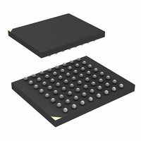
IC FLASH 128MBIT 75NS 64EZBGA
Manufacturer
Numonyx - A DIVISION OF MICRON SEMICONDUCTOR PRODUCTS, INC.
Series
-r
Datasheet
1.RC28F128J3D75B.pdf
(66 pages)
Specifications of RC28F128J3D75D
Format - Memory
FLASH
Memory Type
FLASH
Memory Size
128M (16Mx8, 8Mx16)
Speed
75ns
Interface
Parallel
Voltage - Supply
2.7 V ~ 3.6 V
Operating Temperature
-40°C ~ 85°C
Package / Case
64-EZBGA
Lead Free Status / Rohs Status
Contains lead / RoHS non-compliant
Other names
872828
872828TR
872828TR
RC28F128J3D75 S L8QN
RC28F128J3D75D
RC28F128J3D75DTR
872828TR
872828TR
RC28F128J3D75 S L8QN
RC28F128J3D75D
RC28F128J3D75DTR
Available stocks
Company
Part Number
Manufacturer
Quantity
Price
Company:

Part Number:
RC28F128J3D75D
Manufacturer:
Micron Technology Inc
Quantity:
10 000


Numonyx™ Embedded Flash Memory (J3 v D, Monolithic)
9.1.1
Table 21: Clear Status Register Command Bus-Cycle
Note:
9.2
Table 22: Read Mode Command Bus-Cycles
9.2.1
December 2007
316577-06
Clear Status Register
Read Array
Read Status Register
Read Device Information
CFI Query
Command
Clearing the Status Register
The Status Register (SR) contain Status and error bits which are set by the device. SR
status bits are cleared by the device, however SR error bits are cleared by issuing the
Clear SR command (see
Issuing the Clear SR command places the device in Read SR mode.
Care should be taken to avoid SR ambiguity. If a command sequence error occurs while
in an Erase Suspend condition, the SR will indicate a Command Sequence error by
setting SR.4 and SR.5. When the erase operation is resumed (and finishes), any errors
that may have occurred during the erase operation will be masked by the Command
Sequence error. To avoid this situation, clear the Status Register prior to resuming a
suspended erase operation. The Clear SR command functions independent of the
voltage level on VPEN.
Read Operations
Four types of data can be read from the device: array data, device information, CFI
data, and device status. Upon power-up or return from reset, the device defaults to
Read Array mode. To change the device’s read mode, the appropriate command must
be issued to the device.
device for the desired read mode. The following sections describe each read mode.
Read Array
Upon power-up or return from reset, the device defaults to Read Array mode. Issuing
the Read Array command places the device in Read Array mode. Subsequent reads
output array data on DQ[15:0]. The device remains in Read Array mode until a
different read command is issued, or a program or erase operation is performed, in
which case, the read mode is automatically changed to Read Status.
To change the device to Read Array mode while it is programming or erasing, first issue
the Suspend command. After the operation has been suspended, issue the Read Array
command. When the program or erase operation is subsequently resumed, the device
will automatically revert back to Read Status mode.
Command
Device Address
Address Bus
Table 22
Table
Setup Write Cycle
Device Address
Device Address
Device Address
Device Address
21). Resetting the device also clears the SR.
Address Bus
shows the command codes used to configure the
Setup Write Cycle
Data Bus
0050h
Data Bus
0070h
0090h
0098h
00FFh
Address Bus
Address Bus
---
Confirm Write Cycle
Confirm Write Cycle
---
---
---
---
Data Bus
Data Bus
---
---
---
---
---
Datasheet
37
Related parts for RC28F128J3D75D
Image
Part Number
Description
Manufacturer
Datasheet
Request
R

Part Number:
Description:
IC FLASH 128MBIT 75NS 64EZBGA
Manufacturer:
Numonyx - A DIVISION OF MICRON SEMICONDUCTOR PRODUCTS, INC.
Datasheet:
Part Number:
Description:
IC FLASH 128MBIT 75NS 64EZBGA
Manufacturer:
Numonyx - A DIVISION OF MICRON SEMICONDUCTOR PRODUCTS, INC.
Datasheet:
Part Number:
Description:
IC FLASH 128MBIT 65NS 64EZBGA
Manufacturer:
Numonyx - A DIVISION OF MICRON SEMICONDUCTOR PRODUCTS, INC.
Datasheet:

Part Number:
Description:
IC FLASH 128MBIT 65NM 3V SO16
Manufacturer:
Numonyx - A DIVISION OF MICRON SEMICONDUCTOR PRODUCTS, INC.
Datasheet:
Part Number:
Description:
IC SRL FLASH 128MB NMX 24-BGAS
Manufacturer:
Numonyx - A DIVISION OF MICRON SEMICONDUCTOR PRODUCTS, INC.
Datasheet:
Part Number:
Description:
IC SRL FLASH 128MB NMX 24-BGA
Manufacturer:
Numonyx - A DIVISION OF MICRON SEMICONDUCTOR PRODUCTS, INC.
Datasheet:
Part Number:
Description:
IC SRL FLASH 128MB NMX 16-SOIC
Manufacturer:
Numonyx - A DIVISION OF MICRON SEMICONDUCTOR PRODUCTS, INC.
Datasheet:
Part Number:
Description:
IC SRL FLASH 128MB NMX 8-VDFPN
Manufacturer:
Numonyx - A DIVISION OF MICRON SEMICONDUCTOR PRODUCTS, INC.
Datasheet:
Part Number:
Description:
IC FLASH 128MBIT 75NS 64EZBGA
Manufacturer:
Numonyx - A DIVISION OF MICRON SEMICONDUCTOR PRODUCTS, INC.
Datasheet:
Part Number:
Description:
IC FLASH 32MBIT 75NS 64EZBGA
Manufacturer:
Numonyx - A DIVISION OF MICRON SEMICONDUCTOR PRODUCTS, INC.
Datasheet:
Part Number:
Description:
IC FLASH 32MBIT 75NS 64EZBGA
Manufacturer:
Numonyx - A DIVISION OF MICRON SEMICONDUCTOR PRODUCTS, INC.
Datasheet: