RC28F128J3D75D Numonyx - A DIVISION OF MICRON SEMICONDUCTOR PRODUCTS, INC., RC28F128J3D75D Datasheet - Page 44
RC28F128J3D75D
Manufacturer Part Number
RC28F128J3D75D
Description
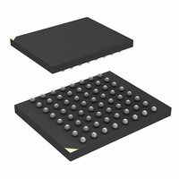
IC FLASH 128MBIT 75NS 64EZBGA
Manufacturer
Numonyx - A DIVISION OF MICRON SEMICONDUCTOR PRODUCTS, INC.
Series
-r
Datasheet
1.RC28F128J3D75B.pdf
(66 pages)
Specifications of RC28F128J3D75D
Format - Memory
FLASH
Memory Type
FLASH
Memory Size
128M (16Mx8, 8Mx16)
Speed
75ns
Interface
Parallel
Voltage - Supply
2.7 V ~ 3.6 V
Operating Temperature
-40°C ~ 85°C
Package / Case
64-EZBGA
Lead Free Status / Rohs Status
Contains lead / RoHS non-compliant
Other names
872828
872828TR
872828TR
RC28F128J3D75 S L8QN
RC28F128J3D75D
RC28F128J3D75DTR
872828TR
872828TR
RC28F128J3D75 S L8QN
RC28F128J3D75D
RC28F128J3D75DTR
Available stocks
Company
Part Number
Manufacturer
Quantity
Price
Company:

Part Number:
RC28F128J3D75D
Manufacturer:
Micron Technology Inc
Quantity:
10 000


9.7.2
9.7.3
9.7.4
9.7.5
Datasheet
44
When the set lock-bit operation is complete, SR.4 should be checked for any error.
When the clear lock-bit operation is complete, SR.5 should be checked for any error.
Errors bits must be cleared using the Clear Status Register command.
Block lock-bit status can be determined by first issuing the Read Device Information
command, and then reading from <block base address> + 02h. DQ0 indicates the lock
status of the addressed block (0 = unlocked, 1 = locked).
Configurable Block Locking
One of the unique new features on the Numonyx™ Embedded Flash Memory (J3 v D,
Monolithic) ,which did not exist on the previous generations of this product family, is
the ability to protect and/or secure the user’s system by offering multiple level of
securities: Non-Volatile Temporary; Non-Volatile Semi-Permanent or Non-Volatile
Permanent. For additional information and collateral request, please contact your filed
representative.
OTP Protection Registers
Numonyx™ Embedded Flash Memory (J3 v D, Monolithic) includes a 128-bit Protection
Register (PR) that can be used to increase the security of a system design. For
example, the number contained in the PR can be used to “match” the flash component
with other system components such as the CPU or ASIC, hence preventing device
substitution.
The 128-bits of the PR are divided into two 64-bit segments:
Reading the OTP Protection Register
The Protection Register is read in Identification Read mode. The device is switched to
this mode by issuing the Read Identifier command (0090h). Once in this mode, read
cycles from addresses shown in
or
information. To return to Read Array mode, write the Read Array command (00FFh).
Programming the OTP Protection Register
PR bits are programmed using the two-cycle Protection Program command. The 64-bit
number is programmed 16 bits at a time for word-wide configuration and eight bits at a
time for byte-wide configuration. First write the Protection Program Setup command,
00C0h. The next write to the device will latch in address and data and program the
specified location. The allowable addresses are shown in
Protection Register Addressing” on page 45
Addressing” on page
on page
PR address space will result in a Status Register error (SR.4 will be set). Attempting to
program a locked PR segment will result in a Status Register error (SR.4 and SR.1 will
be set).
• One segment is programmed at the Numonyx factory with a unique unalterable 64-
• The other segment is left blank for customer designers to program as desired. Once
Table 30, “Byte-Wide Protection Register Addressing”
bit number.
the customer segment is programmed, it can be locked to prevent further
programming.
57. Any attempt to address Protection Program commands outside the defined
46. See
Figure 27, “Protection Register Programming Flowchart”
Table 29, “Word-Wide Protection Register Addressing”
Numonyx™ Embedded Flash Memory (J3 v D, Monolithic)
or
Table 30, “Byte-Wide Protection Register
retrieve the specified
Table 29, “Word-Wide
December 2007
316577-06
Related parts for RC28F128J3D75D
Image
Part Number
Description
Manufacturer
Datasheet
Request
R

Part Number:
Description:
IC FLASH 128MBIT 75NS 64EZBGA
Manufacturer:
Numonyx - A DIVISION OF MICRON SEMICONDUCTOR PRODUCTS, INC.
Datasheet:
Part Number:
Description:
IC FLASH 128MBIT 75NS 64EZBGA
Manufacturer:
Numonyx - A DIVISION OF MICRON SEMICONDUCTOR PRODUCTS, INC.
Datasheet:
Part Number:
Description:
IC FLASH 128MBIT 65NS 64EZBGA
Manufacturer:
Numonyx - A DIVISION OF MICRON SEMICONDUCTOR PRODUCTS, INC.
Datasheet:

Part Number:
Description:
IC FLASH 128MBIT 65NM 3V SO16
Manufacturer:
Numonyx - A DIVISION OF MICRON SEMICONDUCTOR PRODUCTS, INC.
Datasheet:
Part Number:
Description:
IC SRL FLASH 128MB NMX 24-BGAS
Manufacturer:
Numonyx - A DIVISION OF MICRON SEMICONDUCTOR PRODUCTS, INC.
Datasheet:
Part Number:
Description:
IC SRL FLASH 128MB NMX 24-BGA
Manufacturer:
Numonyx - A DIVISION OF MICRON SEMICONDUCTOR PRODUCTS, INC.
Datasheet:
Part Number:
Description:
IC SRL FLASH 128MB NMX 16-SOIC
Manufacturer:
Numonyx - A DIVISION OF MICRON SEMICONDUCTOR PRODUCTS, INC.
Datasheet:
Part Number:
Description:
IC SRL FLASH 128MB NMX 8-VDFPN
Manufacturer:
Numonyx - A DIVISION OF MICRON SEMICONDUCTOR PRODUCTS, INC.
Datasheet:
Part Number:
Description:
IC FLASH 128MBIT 75NS 64EZBGA
Manufacturer:
Numonyx - A DIVISION OF MICRON SEMICONDUCTOR PRODUCTS, INC.
Datasheet:
Part Number:
Description:
IC FLASH 32MBIT 75NS 64EZBGA
Manufacturer:
Numonyx - A DIVISION OF MICRON SEMICONDUCTOR PRODUCTS, INC.
Datasheet:
Part Number:
Description:
IC FLASH 32MBIT 75NS 64EZBGA
Manufacturer:
Numonyx - A DIVISION OF MICRON SEMICONDUCTOR PRODUCTS, INC.
Datasheet: