RC28F128J3D75D Numonyx - A DIVISION OF MICRON SEMICONDUCTOR PRODUCTS, INC., RC28F128J3D75D Datasheet - Page 43
RC28F128J3D75D
Manufacturer Part Number
RC28F128J3D75D
Description
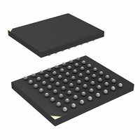
IC FLASH 128MBIT 75NS 64EZBGA
Manufacturer
Numonyx - A DIVISION OF MICRON SEMICONDUCTOR PRODUCTS, INC.
Series
-r
Datasheet
1.RC28F128J3D75B.pdf
(66 pages)
Specifications of RC28F128J3D75D
Format - Memory
FLASH
Memory Type
FLASH
Memory Size
128M (16Mx8, 8Mx16)
Speed
75ns
Interface
Parallel
Voltage - Supply
2.7 V ~ 3.6 V
Operating Temperature
-40°C ~ 85°C
Package / Case
64-EZBGA
Lead Free Status / Rohs Status
Contains lead / RoHS non-compliant
Other names
872828
872828TR
872828TR
RC28F128J3D75 S L8QN
RC28F128J3D75D
RC28F128J3D75DTR
872828TR
872828TR
RC28F128J3D75 S L8QN
RC28F128J3D75D
RC28F128J3D75DTR
Available stocks
Company
Part Number
Manufacturer
Quantity
Price
Company:

Part Number:
RC28F128J3D75D
Manufacturer:
Micron Technology Inc
Quantity:
10 000


Numonyx™ Embedded Flash Memory (J3 v D, Monolithic)
Table 27: STS Configuration Coding Definitions
9.7
9.7.1
Table 28: Block Locking Command Bus-Cycles
December 2007
316577-06
Notes:
1.
2.
3.
Set Block Lock Bit
Clear Block Lock Bits
11 = pulse on Erase or Program Complete
D[1:0] = STS Configuration Codes
D7
10 = pulse on Program Complete
01 = pulse on Erase Complete
When configured in one of the pulse modes, STS pulses low with a typical pulse width of 500 ns.
An invalid configuration code will result in both SR.4 and SR.5 being set.
Reserved bits are invalid should be ignored.
00 = default, level mode;
device ready indication
Security and Protection
Numonyx™ Embedded Flash Memory (J3 v D) device offer both hardware and software
security features. Block lock operations, PRs and VPEN allow users to implement
various levels of data protection.
Normal Block Locking
Numonyx™ Embedded Flash Memory (J3 v D, Monolithic) has the unique capability of
Flexible Block Locking (locked blocks remain locked upon reset or power cycle): All
blocks are unlocked at the factory. Blocks can be locked individually by issuing the Set
Block Lock Bit command sequence to any address within a block. Once locked, blocks
remain locked when power is removed, or when the device is reset.
All locked blocks are unlocked simultaneously by issuing the Clear Block Lock Bits
command sequence to any device address. Locked blocks cannot be erased or
programmed.
After issuing the Set Block Lock Bit setup command or Clear Block Lock Bits setup
command, the device’s read mode is automatically changed to Read Status Register
mode. After issuing the confirm command, completion of the operation is indicated by
STS (in RY/BY# mode) going high and SR.7 = 1.
Blocks cannot be locked or unlocked while programming or erasing, or while the device
is suspended. Reliable block lock and unlock operations occur only when V
are valid. When V
Command
D6
Table 28
D5
PEN
Reserved
≤ V
summarizes the command bus-cycles.
Controls HOLD to a memory controller to prevent accessing a flash memory
subsystem while any flash device's WSM is busy.
Generates a system interrupt pulse when any flash device in an array has
completed a block erase. Helpful for reformatting blocks after file system free
space reclamation or “cleanup.”
Not supported on this device.
Generates system interrupts to trigger servicing of flash arrays when either
erase or program operations are completed, when a common interrupt service
routine is desired.
PENLK
3
Device Address
Block Address
D4
Address Bus
, block lock-bits cannot be changed.
Setup Write Cycle
D3
Data Bus
0060h
0060h
Notes
D2
Device Address
Block Address
Address Bus
Confirm Write Cycle
Complete
Pulse on
Program
(1)
D1
CC
Data Bus
Complete
Pulse on
and V
00D0h
0001h
Erase
Datasheet
(1)
D0
PEN
43
Related parts for RC28F128J3D75D
Image
Part Number
Description
Manufacturer
Datasheet
Request
R

Part Number:
Description:
IC FLASH 128MBIT 75NS 64EZBGA
Manufacturer:
Numonyx - A DIVISION OF MICRON SEMICONDUCTOR PRODUCTS, INC.
Datasheet:
Part Number:
Description:
IC FLASH 128MBIT 75NS 64EZBGA
Manufacturer:
Numonyx - A DIVISION OF MICRON SEMICONDUCTOR PRODUCTS, INC.
Datasheet:
Part Number:
Description:
IC FLASH 128MBIT 65NS 64EZBGA
Manufacturer:
Numonyx - A DIVISION OF MICRON SEMICONDUCTOR PRODUCTS, INC.
Datasheet:

Part Number:
Description:
IC FLASH 128MBIT 65NM 3V SO16
Manufacturer:
Numonyx - A DIVISION OF MICRON SEMICONDUCTOR PRODUCTS, INC.
Datasheet:
Part Number:
Description:
IC SRL FLASH 128MB NMX 24-BGAS
Manufacturer:
Numonyx - A DIVISION OF MICRON SEMICONDUCTOR PRODUCTS, INC.
Datasheet:
Part Number:
Description:
IC SRL FLASH 128MB NMX 24-BGA
Manufacturer:
Numonyx - A DIVISION OF MICRON SEMICONDUCTOR PRODUCTS, INC.
Datasheet:
Part Number:
Description:
IC SRL FLASH 128MB NMX 16-SOIC
Manufacturer:
Numonyx - A DIVISION OF MICRON SEMICONDUCTOR PRODUCTS, INC.
Datasheet:
Part Number:
Description:
IC SRL FLASH 128MB NMX 8-VDFPN
Manufacturer:
Numonyx - A DIVISION OF MICRON SEMICONDUCTOR PRODUCTS, INC.
Datasheet:
Part Number:
Description:
IC FLASH 128MBIT 75NS 64EZBGA
Manufacturer:
Numonyx - A DIVISION OF MICRON SEMICONDUCTOR PRODUCTS, INC.
Datasheet:
Part Number:
Description:
IC FLASH 32MBIT 75NS 64EZBGA
Manufacturer:
Numonyx - A DIVISION OF MICRON SEMICONDUCTOR PRODUCTS, INC.
Datasheet:
Part Number:
Description:
IC FLASH 32MBIT 75NS 64EZBGA
Manufacturer:
Numonyx - A DIVISION OF MICRON SEMICONDUCTOR PRODUCTS, INC.
Datasheet: