TDA1517P NXP Semiconductors, TDA1517P Datasheet
TDA1517P
Specifications of TDA1517P
Available stocks


Related parts for TDA1517P


TDA1517P Summary of contents
Page 1
... DATA SHEET TDA1517; TDA1517P stereo power amplifier Product specification Supersedes data of 2002 Jan 17 INTEGRATED CIRCUITS 2004 Feb 18 ...
Page 2
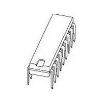
... kHz i PACKAGE DESCRIPTION plastic single in-line medium power package with fin; 9 leads plastic rectangular-bent single in-line medium power package with fin; 9 leads plastic heat-dissipating dual in-line package; 18 leads 2 Product specification TDA1517; TDA1517P MIN. TYP. MAX. UNIT 6.0 14.4 18.0 V − ...
Page 3
... VA 60 kΩ mute switch input signal voltage ground SGND Fig.1 Block diagram. 3 Product specification TDA1517; TDA1517P 4 output 1 power stage 8 mute/stand-by switch input stand-by reference voltage mute switch TDA1517 6 output 2 power stage power ground (substrate) 5 MLC351 PGND ...
Page 4
... MLC352 Pins should be connected to GND or floating. 4 Product specification TDA1517; TDA1517P DESCRIPTION INV1 1 18 SGND 2 17 SVRR 3 16 OUT1 4 15 PGND 5 TDA1517P 14 ...
Page 5
... Fig.4 Power derating curve. 2004 Feb 18 operating no signal see Fig.4 PARAMETER thermal resistance from junction to pins thermal resistance from junction to ambient MLC354 100 150 amb 5 TDA1517; TDA1517P CONDITIONS MIN. − − − − − − − − −55 −40 − VALUE Product specification MAX. ...
Page 6
... Standby condition I DC current in standby condition sb V switch-on current sw Note 1. The circuit is DC adjusted at V 2004 Feb 18 CONDITIONS note 1 see Fig I(max and AC operating TDA1517; TDA1517P MIN. TYP. 6.0 14.4 − 40 − 6.95 − 8.5 − − kHz i − − − ...
Page 7
... Fig.6; unless otherwise specified. amb CONDITIONS THD = 0.5%; note 1 THD = 10%; note −3 dB; note 2 at −1 dB note Ω; note Ω; note note Ω V Product specification TDA1517; TDA1517P MIN. TYP. MAX. − − 5.5 6.0 − − 0.1 − − 45 − − − − 48 − − ...
Page 8
... Feb 18 MLC355 100 μA) 100 μF 3 input internal reference 1 voltage TDA1517 kΩ 1000 μF signal power ground ground Fig.6 Application circuit diagram. 8 TDA1517; TDA1517P standby switch 100 kΩ 220 nF 9 input 2 6 MLC356 1000 μF Product specification V P 2200 μF ...
Page 9
... Feb scale (1) ( 0.67 1.40 0.48 21.8 21.4 6.48 2.54 0.50 1.14 0.38 21.4 20.7 6.20 REFERENCES JEDEC JEITA 9 Product specification TDA1517; TDA1517P 3.9 2.75 3.4 1.75 15.1 4.4 3.4 2.50 3.2 1.55 14.9 4.2 EUROPEAN PROJECTION SOT110 ( max. 5.9 0. ...
Page 10
... Feb scale (2) ( 1.40 0.48 21.8 21.4 6.48 2.54 1.14 0.38 21.4 20.7 6.20 REFERENCES JEDEC JEITA 10 TDA1517; TDA1517P seating plane 3.8 2.75 3.4 1.75 15.1 4.4 5.9 3.3 2.50 3.2 1.55 14.9 4.2 5.7 EUROPEAN PROJECTION Product specification SOT352-1 E (2) Z ...
Page 11
... Feb scale ( 1.40 0.67 1.05 0.47 21.85 1.14 0.50 0.75 0.38 21.35 0.06 0.03 0.04 0.02 0.87 0.04 0.02 0.03 0.01 0.84 REFERENCES JEDEC JEITA 11 TDA1517; TDA1517P ( 6.5 3.9 8.32 2.54 7.62 6.2 3.1 8.02 0.26 0.15 0.33 0.1 0.3 0.24 ...
Page 12
... If the temperature of the soldering iron bit is less than 300 °C it may remain in contact for seconds. If the bit temperature is between 300 and 400 °C, contact may seconds. SOLDERING METHOD DIPPING − suitable − 12 Product specification TDA1517; TDA1517P ). If the stg(max) WAVE suitable (1) suitable not suitable ...
Page 13
... NXP Semiconductors products in order to avoid a default of the applications and the products or of the application or use by customer’s third party customer(s). NXP does not accept any liability in this respect. 13 Product specification TDA1517; TDA1517P DEFINITION ...
Page 14
... Export might require a prior authorization from national authorities. 2004 Feb 18 TDA1517; TDA1517P Quick reference data ⎯ The Quick reference data is an extract of the product data given in the Limiting values and Characteristics sections of this document, and as such is not complete, exhaustive or legally binding. Non-automotive qualified products ⎯ ...
Page 15
... RF, Analog, Power Management, Interface, Security and Digital Processing expertise Customer notification This data sheet was changed to reflect the new company name NXP Semiconductors. No changes were made to the content, except for the legal definitions and disclaimers. Contact information For additional information please visit: http://www ...