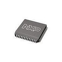
SC28C94A1A NXP Semiconductors, SC28C94A1A Datasheet - Page 36

SC28C94A1A
Manufacturer Part Number
SC28C94A1A
Description
UART Interface IC UART QUAD W/FIFO
Manufacturer
NXP Semiconductors
Type
Quad UARTr
Datasheet
1.SC28C94A1A512.pdf
(39 pages)
Specifications of SC28C94A1A
Number Of Channels
4
Data Rate
1 Mbps
Supply Voltage (max)
5.5 V
Supply Voltage (min)
4.5 V
Supply Current
35 mA
Maximum Operating Temperature
+ 85 C
Minimum Operating Temperature
- 40 C
Package / Case
PLCC-52
Description/function
Quad UART
Mounting Style
SMD/SMT
Operating Supply Voltage
5 V
Lead Free Status / Rohs Status
Details
Other names
SC28C94A1A,512
Available stocks
Company
Part Number
Manufacturer
Quantity
Price
Company:
Part Number:
SC28C94A1A,512
Manufacturer:
NXP Semiconductors
Quantity:
10 000
Company:
Part Number:
SC28C94A1A,518
Manufacturer:
Maxim
Quantity:
21
Company:
Part Number:
SC28C94A1A,518
Manufacturer:
NXP Semiconductors
Quantity:
10 000
Philips Semiconductors
addressed register. The generation of DACKN begins with the start
of a bus cycle (Read, Write or Interrupt Acknowledge) and then
requires two edges of the X1 clock plus typically 70ns for its
assertion.
In this mode the writing of data to the QUART registers occurs on
the falling edge of DACKN or the rising edge of the combination of
CEN and WRN which ever occurs first. This requires that the data
to be written to the QUART registers be valid with respect to the
leading edge of the combination of CEN and WRN. (In the
synchronous mode it is the trailing edge)
IACKN updates the CIR (Current Interrupt Register) and places the
Interrupt Vector or Modified Interrupt Vector on the bus if the
Interrupt Vector is used.
The Synchronous Interface
In this mode the DACKN and IACKN are usually not used. Here
data is written to the QUART on the trailing edge of the
combination of CEN and WRN. The placing of data on the bus
during a read cycle begins with the leading edge of the combination
of CEN and RDN.
The read cycle will terminate with the rise of CEN or RDN which
ever one occurs first. In this mode bus cycles are usually setup to be
the minimum time required by the QUART and hence will be faster
than bus cycles that are defined by the DACKN signal. DACKN
should be turned off in this mode.
2006 Aug 09
Quad universal asynchronous receiver/transmitter (QUART)
36
The synchronous mode usually will not use the IACKN and DACKN.
When IACKN is not used or is not available the command at 2Ah
should be used to update the CIR (Current Interrupt Register). This
register is normally updated by IACKN in response to the IRQN.
Note that the CIR is not updated by IRQN since there could be a
long time between the assertion of IRQN and the start of the
interrupt service routine. During this time it is quite possible that
another interrupt with a higher priority occurs. It is the CIR that
contains the information that describes the interrupt source and its
priority. It is therefor recommended that the first operation upon
entering the interrupt service routine is the updating of the CIR.
(Recall that the contents of the GLOBAL registers reflect the content
of the CIR)
Summary
In the asynchronous mode all of the interface pins are usually used.
However there is no conflict in the quart if both modes are used in
the same application. (i.e. More than one device may control the
QUART) The principles to keep in mind are:
1. When IACKN is not used the CIR should be updated via
2. If DACKN is not used it should be disabled.
3. When in the asynchronous mode be sure DACKN is enabled.
4. With 68xxx type controllers the RDN signal must be generated.
command.
SC28C94
Product data sheet


