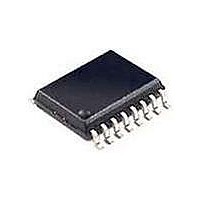
SI3201-KS Silicon Laboratories Inc, SI3201-KS Datasheet - Page 45

SI3201-KS
Manufacturer Part Number
SI3201-KS
Description
IC LINEFEED INTRFC SI321X 16SOIC
Manufacturer
Silicon Laboratories Inc
Series
ProSLIC®r
Datasheet
1.SI3201-KS.pdf
(138 pages)
Specifications of SI3201-KS
Package / Case
16-SOIC (3.9mm Width) Exposed Pad, 16-eSOIC, 16-HSOIC
Function
CODEC
Interface
PCM, Serial, SPI
Number Of Circuits
1
Voltage - Supply
3.13 V ~ 5.25 V
Current - Supply
88mA
Power (watts)
800mW
Operating Temperature
0°C ~ 70°C
Mounting Type
Surface Mount
Includes
BORSCHT Functions, Ring Trip Detection
Product
SLIC
Supply Voltage (min)
3.13 V
Supply Current
88 mA
Maximum Operating Temperature
+ 70 C
Minimum Operating Temperature
0 C
Mounting Style
SMD/SMT
Lead Free Status / RoHS Status
Contains lead / RoHS non-compliant
Available stocks
Company
Part Number
Manufacturer
Quantity
Price
Part Number:
SI3201-KS
Manufacturer:
SILICONIX
Quantity:
20 000
Company:
Part Number:
SI3201-KSR
Manufacturer:
ELANTEC
Quantity:
50 000
Part Number:
SI3201-KSR
Manufacturer:
SILICON LABS/芯科
Quantity:
20 000
where:
N
I
(max value = 2 mA), and
V
It is good practice to provide a buffer of a few more
milliamperes for I
leakages, etc. The total I
smaller than 80 mA.
where
transistors Q5 and Q6.
The minimum value for V
following:
The ProSLIC is designed to create a fully-balanced
ringing waveform, meaning that the TIP and RING
common mode voltage, (V
voltage
automatically set to the following:
VCMR is an indirect register, which provides the
headroom by the ringing waveform with respect to the
V
Register 40 with an LSB voltage of 1.5 V/LSB.
Register 40 should be set with the calculated V
provide voltage headroom during ringing.
Silicon revisions C and higher support the option to
briefly increase the maximum differential current limit
between the voltage transition of TIP and RING from
OS
AC,PK
REN
BATH
is the offset current flowing in the line driver circuit
LCS
is the ringing REN load (max value = 5),
V
rail. The value is set as a 4-bit setting in indirect
= amplitude of the ac ringing waveform.
OVR
is
VBATH
is the minimum expected current gain of
VCM_RING
Processor
=
referred
Signal
Input
I
LOAD , PK
LFS
LOAD,PK
=
V
AC , PK
=
ISP_OUT
to
------------ -
BATH
VBATH VCMR
--------------------------------------------- -
TIP
to account for possible line
+
+
LOAD,PK
as
1
V
+ V
ROFF
is therefore given by the
2
80.6
VCM_RING
–
RING
Digital
NRTP
+
LPF
current should be
V
)/2, is fixed. This
OVR
+
Figure 23. Ring Trip Detector
1 V
Threshold
Ring Trip
RPTP
and
OVR
Rev. 1.45
–
+
to
is
ringing to a dc linefeed state. This mode is enabled by
setting ILIMEN = 1 (direct Register 108, bit 7).
2.4.6. Ring Trip Detection
A ring trip event signals that the terminal equipment has
gone off-hook during the ringing state. The ProSLIC
performs ring trip detection digitally using its on-chip A/
D converter. The functional blocks required to
implement ring trip detection are shown in Figure 23.
The primary input to the system is the loop current
sense (LCS) value provided by the current monitoring
circuitry and reported in direct Register 79. LCS data is
processed by the input signal processor when the
ProSLIC is in the ringing state as indicated by the
Linefeed Shadow register (direct Register 64). The data
then feeds into a programmable digital low-pass filter
that removes unwanted ac signal components before
threshold detection.
The output of the low-pass filter is compared to a
programmable threshold, RPTP (indirect Register 29).
The threshold comparator output feeds a programmable
debouncing filter. The output of the debouncing filter
remains in its present state unless the input remains in
the opposite state for the entire period of time
programmed by the ring trip debounce interval,
RTDI[6:0] (direct Register 70). If the debounce interval
has been satisfied, the RTP bit of direct Register 68 will
be set to indicate that a valid ring trip has occurred. A
ring trip interrupt is generated if enabled by the RTIE bit
(direct Register 22). Table 31 lists the registers that
must be written or monitored to correctly detect a ring
trip condition.
The recommended values for RPTP, NRTP, and RTDI
vary according to the programmed ringing frequency.
Register values for various ringing frequencies are
given in Table 32.
DBIRAW
Debounce
Filter
RTDI
Si3210/Si3211
RTP
Interrupt
Logic
RTIE
RTIP
45


