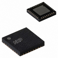
SC16IS752IBS,151 NXP Semiconductors, SC16IS752IBS,151 Datasheet - Page 29

SC16IS752IBS,151
Manufacturer Part Number
SC16IS752IBS,151
Description
IC UART DUAL I2C/SPI 32-HVQFN
Manufacturer
NXP Semiconductors
Type
IrDA or RS- 232 or RS- 485r
Datasheet
1.SC16IS752IBS151.pdf
(59 pages)
Specifications of SC16IS752IBS,151
Number Of Channels
2, DUART
Package / Case
32-VFQFN Exposed Pad
Features
Low Current
Fifo's
64 Byte
Protocol
RS232, RS485
Voltage - Supply
2.5V, 3.3V
With Auto Flow Control
Yes
With Irda Encoder/decoder
Yes
With False Start Bit Detection
Yes
With Modem Control
Yes
Mounting Type
Surface Mount
Data Rate
5 Mbps
Supply Voltage (max)
3.6 V
Supply Voltage (min)
2.3 V
Supply Current
6 mA
Maximum Operating Temperature
+ 95 C
Minimum Operating Temperature
- 40 C
Mounting Style
SMD/SMT
Operating Supply Voltage
2.5 V or 3.3 V
Lead Free Status / RoHS Status
Lead free / RoHS Compliant
For Use With
568-4000 - DEMO BOARD SPI/I2C TO DUAL UART568-3510 - DEMO BOARD SPI/I2C TO UART
Lead Free Status / Rohs Status
Lead free / RoHS Compliant
Other names
568-2236
935279288151
SC16IS752IBS-S
935279288151
SC16IS752IBS-S
NXP Semiconductors
SC16IS752_SC16IS762_7
Product data sheet
8.11 Transmission Control Register (TCR)
8.12 Trigger Level Register (TLR)
This 8-bit register is used to store the RX FIFO threshold levels to stop/start transmission
during hardware/software flow control.
settings. If TCR bits are cleared, then selectable trigger levels in FCR are used in place of
TCR.
Table 22.
TCR trigger levels are available from 0 bytes to 60 characters with a granularity of four.
Remark: TCR can only be written to when EFR[4] = logic 1 and MCR[2] = logic 1. The
programmer must program the TCR such that TCR[3:0] > TCR[7:4]. There is no built-in
hardware check to make sure this condition is met. Also, the TCR must be programmed
with this condition before Auto-RTS or software flow control is enabled to avoid spurious
operation of the device.
This 8-bit register is used to store the transmit and received FIFO trigger levels used for
interrupt generation. Trigger levels from 4 to 60 can be programmed with a granularity
of four.
Table 23.
Remark: TLR can only be written to when EFR[4] = logic 1 and MCR[2] = logic 1. If
TLR[3:0] or TLR[7:4] are logical 0, the selectable trigger levels via the FIFO Control
Register (FCR) are used for the transmit and receive FIFO trigger levels. Trigger levels
from 4 characters to 60 characters are available with a granularity of four. The TLR should
be programmed for
When the trigger level setting in TLR is zero, the SC16IS752/SC16IS762 uses the trigger
level setting defined in FCR. If TLR has non-zero trigger level value, the trigger level
defined in FCR is discarded. This applies to both transmit FIFO and receive FIFO trigger
level setting.
When TLR is used for RX trigger level control, FCR[7:6] should be left at the default state
‘00’.
Bit
7:4
3:0
Bit
7:4
3:0
Table 23
Symbol
TCR[7:4]
TCR[3:0]
Symbol
TLR[7:4]
TLR[3:0]
Transmission Control Register bits description
Trigger Level Register bits description
shows Trigger Level Register bit settings.
N
4
, where N is the desired trigger level.
Dual UART with I
Rev. 07 — 19 May 2008
Description
RX FIFO trigger level to resume
RX FIFO trigger level to halt transmission
Description
RX FIFO trigger levels (4 to 60), number of characters available
TX FIFO trigger levels (4 to 60), number of spaces available
Table 22
2
SC16IS752/SC16IS762
C-bus/SPI interface, 64-byte FIFOs, IrDA SIR
shows Transmission Control Register bit
© NXP B.V. 2008. All rights reserved.
29 of 59


