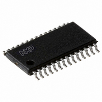
SC16IS752IPW,112 NXP Semiconductors, SC16IS752IPW,112 Datasheet - Page 13

SC16IS752IPW,112
Manufacturer Part Number
SC16IS752IPW,112
Description
IC UART DUAL 12C/SPI 28TSSOP
Manufacturer
NXP Semiconductors
Type
IrDA or RS- 232 or RS- 485r
Datasheet
1.SC16IS752IBS151.pdf
(59 pages)
Specifications of SC16IS752IPW,112
Number Of Channels
2, DUART
Package / Case
28-TSSOP (0.173", 4.40mm Width)
Features
Low Current
Fifo's
64 Byte
Protocol
RS232, RS485
Voltage - Supply
2.5V, 3.3V
With Auto Flow Control
Yes
With Irda Encoder/decoder
Yes
With False Start Bit Detection
Yes
With Modem Control
Yes
Mounting Type
Surface Mount
Data Rate
5 Mbps
Supply Voltage (max)
3.6 V
Supply Voltage (min)
2.3 V
Supply Current
6 mA
Maximum Operating Temperature
+ 95 C
Minimum Operating Temperature
- 40 C
Mounting Style
SMD/SMT
Operating Supply Voltage
2.5 V or 3.3 V
Lead Free Status / RoHS Status
Lead free / RoHS Compliant
For Use With
568-4000 - DEMO BOARD SPI/I2C TO DUAL UART568-3510 - DEMO BOARD SPI/I2C TO UART
Lead Free Status / Rohs Status
Lead free / RoHS Compliant
Other names
568-4016-5
935279292112
SC16IS752IPW
SC16IS752IPW
935279292112
SC16IS752IPW
SC16IS752IPW
NXP Semiconductors
SC16IS752_SC16IS762_7
Product data sheet
7.4 Hardware Reset, Power-On Reset (POR) and Software Reset
These three reset methods are identical and will reset the internal registers as indicated in
Table
Table 4
Table 4.
Remark: Registers DLL, DLH, SPR, XON1, XON2, XOFF1, XOFF2 are not reset by the
top-level reset signal RESET, POR and Software Reset, that is, they hold their
initialization values during reset.
Table 5
Table 5.
Register
Interrupt Enable Register
Interrupt Identification Register
FIFO Control Register
Line Control Register
Modem Control Register
Line Status Register
Modem Status Register
Enhanced Features Register
Receive Holding Register
Transmit Holding Register
Transmission Control Register
Trigger Level Register
Transmit FIFO level
Receive FIFO level
I/O direction
I/O interrupt enable
I/O control
Extra Features Control Register
Signal
TX
RTS
I/Os
IRQ
4.
summarizes the state of register after reset.
summarizes the state of output signals after reset.
Register reset
Output signals after reset
Reset state
HIGH
HIGH
inputs
HIGH by external pull-up
Dual UART with I
Rev. 07 — 19 May 2008
Reset state
all bits cleared
bit 0 is set; all other bits cleared
all bits cleared
reset to 0001 1101 (0x1D)
all bits cleared
bit 5 and bit 6 set; all other bits cleared
bits 3:0 cleared; bits 7:4 input signals
all bits cleared
pointer logic cleared
pointer logic cleared
all bits cleared
all bits cleared
reset to 0100 0000 (0x40)
all bits cleared
all bits cleared
all bits cleared
all bits cleared
all bits cleared
2
SC16IS752/SC16IS762
C-bus/SPI interface, 64-byte FIFOs, IrDA SIR
© NXP B.V. 2008. All rights reserved.
13 of 59


