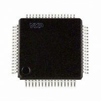
SC16C654DBIB64,128 NXP Semiconductors, SC16C654DBIB64,128 Datasheet - Page 31

SC16C654DBIB64,128
Manufacturer Part Number
SC16C654DBIB64,128
Description
IC QUAD UART 64BYTE 64LQFP
Manufacturer
NXP Semiconductors
Datasheet
1.SC16C654BIBS528.pdf
(58 pages)
Specifications of SC16C654DBIB64,128
Number Of Channels
4, QUART
Fifo's
64 Byte
Voltage - Supply
2.5V, 3.3V, 5V
With Auto Flow Control
Yes
With Irda Encoder/decoder
Yes
With False Start Bit Detection
Yes
With Modem Control
Yes
With Cmos
Yes
Mounting Type
Surface Mount
Package / Case
64-LQFP
Lead Free Status / RoHS Status
Lead free / RoHS Compliant
Other names
935276671128
SC16C654DBIB64-F
SC16C654DBIB64-F
SC16C654DBIB64-F
SC16C654DBIB64-F
Available stocks
Company
Part Number
Manufacturer
Quantity
Price
Company:
Part Number:
SC16C654DBIB64,128
Manufacturer:
NXP Semiconductors
Quantity:
10 000
Philips Semiconductors
9397 750 14965
Product data sheet
7.6 Modem Control Register (MCR)
Table 16:
Table 17:
Table 18:
This register controls the interface with the modem or a peripheral device.
Table 19:
LCR[5]
X
0
0
1
1
LCR[2]
0
1
1
LCR[1]
0
0
1
1
Bit
7
6
5
Symbol
MCR[7]
MCR[6]
MCR[5]
LCR[5] parity selection
LCR[2] stop bit length
LCR[1:0] word length
Modem Control Register bits description
LCR[4]
X
0
1
0
1
Word length
5, 6, 7, 8
5
6, 7, 8
LCR[0]
0
1
0
1
Description
Clock select.
IR enable.
Xon Any.
5 V, 3.3 V and 2.5 V quad UART, 5 Mbit/s (max.) with 64-byte FIFOs
logic 0 = divide-by-1. The input clock (crystal or external) is divided by 16
and then presented to the Programmable Baud Rate Generator (BGR)
without further modification, that is, divide-by-1. (normal default condition).
logic 1 = divide-by-4. The divide-by-1 clock described in MCR[7] = a logic 0,
if further divided by four. Also see
generator”.
logic 0 = enable the standard modem receive and transmit input/output
interface (normal default condition)
logic 1 = enable infrared IrDA receive and transmit inputs/outputs. While in
this mode, the TX/RX output/inputs are routed to the infrared
encoder/decoder. The data input and output levels will conform to the IrDA
infrared interface requirement. As such, while in this mode, the infrared TX
output will be a logic 0 during idle data conditions.
logic 0 = disable Xon Any function (for 16C554 compatibility) (normal default
condition)
logic 1 = enable Xon Any function. In this mode, any RX character received
will enable Xon
Rev. 02 — 20 June 2005
LCR[3]
0
1
1
1
1
Word length
5
6
7
8
Stop bit length (bit times)
1
1
2
1
2
Parity selection
no parity
odd parity
even parity
forced parity ‘1’
forced parity ‘0’
SC16C654B/654DB
Section 6.9 “Programmable baud rate
© Koninklijke Philips Electronics N.V. 2005. All rights reserved.
31 of 58


