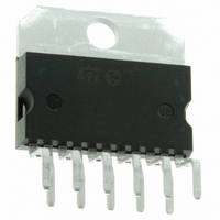
TDA7360 STMicroelectronics, TDA7360 Datasheet - Page 15

TDA7360
Manufacturer Part Number
TDA7360
Description
IC AMP AUDIO PWR 22W MULTIWATT11
Manufacturer
STMicroelectronics
Type
Class ABr
Datasheet
1.TDA7360.pdf
(30 pages)
Specifications of TDA7360
Output Type
1-Channel (Mono) or 2-Channel (Stereo)
Max Output Power X Channels @ Load
22W x 1 @ 3.2 Ohm; 12W x 2 @ 1.6 Ohm
Voltage - Supply
8 V ~ 18 V
Features
Depop, Short-Circuit and Thermal Protection, Standby
Mounting Type
Through Hole
Package / Case
Multiwatt-11 (Vertical, Bent and Staggered Leads)
Operational Class
Class-AB
Output Power (typ)
22W
Audio Amplifier Function
Speaker
Total Harmonic Distortion
0.05%%
Single Supply Voltage (typ)
9/12/15V
Dual Supply Voltage (typ)
Not RequiredV
Power Supply Requirement
Single
Power Dissipation
36W
Rail/rail I/o Type
No
Power Supply Rejection Ratio
62dB
Single Supply Voltage (min)
8V
Single Supply Voltage (max)
18V
Dual Supply Voltage (min)
Not RequiredV
Dual Supply Voltage (max)
Not RequiredV
Operating Temp Range
-40C to 150C
Operating Temperature Classification
Automotive
Mounting
Through Hole
Pin Count
11 +Tab
Package Type
MULTIWATT V
Lead Free Status / RoHS Status
Lead free / RoHS Compliant
Other names
497-3973-5
Available stocks
Company
Part Number
Manufacturer
Quantity
Price
Part Number:
TDA7360
Manufacturer:
ST
Quantity:
20 000
TDA7360
3
3.1
3.2
3.2.1
3.2.2
3.2.3
General description
Amplifier organization
The TDA7360 has been developed taking care of the key concepts of the modern power
audio amplifier for car radio such as: space and costs saving due to the minimized external
count, excellent electrical performances, flexibility in use, superior reliability thanks to a built-
in array of protections. As a result the following performances has been achieved:
Block description
Polarization
The device is organized with the gain resistors directly connected to the signal ground pin
i.e. without gain capacitors
The non inverting inputs of the amplifiers are connected to the SVR pin by means of resistor
dividers, equal to the feedback networks. This allows the outputs to track the SVR pin which
is sufficiently slow to avoid audible turn-on and turn-off transients.
SVR
The voltage ripple on the outputs is equal to the one on SVR pin: with appropriate selection
of CSVR, more than 60dB of ripple rejection can be obtained.
Delayed turn-on (muting)
The C
the voltage on SVR pin reaches ~2.5V typ
duplicating the input differential pair
an internal mute input. This feature is necessary to prevent transients at the inputs reaching
the loudspeaker(s) immediately after power-on).
Figure 1
At the power-on the output decoupling capacitors are charged through an internal path but
the device itself remains switched off (Phase 1 of the represented diagram).
–
–
–
–
–
–
–
–
–
–
SVR
represents the detailed turn-on transient with reference to the stereo configuration.
No need of bootstrap capacitors even at the highest output power levels
Absolute stability without external compensation thanks to the innovative out stage
configuration, also allowing internally fixed closed loop lower than competitors
Low gain (20 dB stereo fixed without any external components) in order to
minimize the output noise and optimize SVR
Silent Mute/Standby function featuring absence of pop ON/OFF noise
high SVR
Stereo/bridge operation without addition of external component
AC/DC short circuit protection (to GND, to V
Loudspeaker protection
Dump protection
ESD protection
sets a signal turn-on delay too. A circuit is included which mutes the device until
(Figure
Doc ID 1499 Rev 3
1).
(Figure
(Figure
27): it can be switched to the signal source or to
1). The mute function is obtained by
S
, across the load)
General description
15/30


