LM49370RL/NOPB National Semiconductor, LM49370RL/NOPB Datasheet - Page 48
LM49370RL/NOPB
Manufacturer Part Number
LM49370RL/NOPB
Description
IC AUDIO SUBSYSTEM 1.2W 49USMDXT
Manufacturer
National Semiconductor
Series
Boomer®, PowerWise®r
Type
Class Dr
Datasheet
1.LM49370RLNOPB.pdf
(100 pages)
Specifications of LM49370RL/NOPB
Output Type
1-Channel (Mono) with Mono and Stereo Headphones
Max Output Power X Channels @ Load
1.2W x 1 @ 8 Ohm; 52mW x 2 @ 16 Ohm
Voltage - Supply
2.5 V ~ 5.5 V
Features
3D, Depop, I²C, I²S, Microphone, Mute, PCM, Shutdown, SPI, Standby, Volume Control
Mounting Type
Surface Mount
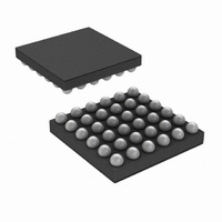
Package / Case
49-MicroSMDxt
Dc
07+
For Use With
LM49370RLEVAL - BOARD EVALUATION LM49370RL
Lead Free Status / RoHS Status
Lead free / RoHS Compliant
Other names
LM49370RLTR


www.national.com
Bits
3:2
5:4
0
1
6
7
12.31 3D CONFIGURATION REGISTER
This register is used to control the configuration of the 3D circuit.
CUST_COMP
ATTENUATE
3D_TYPE
3D_ENB
LEVEL
FREQ
Field
Setting this bit enables the 3D effect. When cleared to zero, the 3D effect is disabled and the 3D module
then passes the I
unaffected by the 3D module.
This bit selects between type 1 and type 2 3D sound effect. Clearing this bit to zero selects type 1 effect
and setting it to one selects type 2.
Type1: Rout = Ri-G*Lout3d, Lout = Li-G*Rout3d
Type2: Rout = -Ri-G*Lout3d, Lout = Li+G*Rout3d
where,
Ri = Right I
Li = Left I
G = 3D gain level (Mix ratio)
Rout3d = Ri filtered through a high-pass filter with a corner frequency controlled by FREQ
Lout3d = Li filtered through a high-pass filter with a corner frequency controlled by FREQ
This programs the level of 3D effect that is applied.
This programs the HPF rolloff (-3dB) frequency of the 3D effect.
Clearing this bit to zero maintains the level of the left and right input channels at the output. Setting this
bit to one attenuates the output level by 50%.
This may be appropriate for high level audio inputs when type 2 3D effect is used. Type 2 effect involves
adding the same polarity of left and right inputs to give the final outputs. Type 2 effect has the potential
for creating a clipping condition, however this bit offers an alternative to clipping.
If set, the DAC compensation filter may be programmed by the user through registers (0x20h) to( 0x25h).
Otherwise, the defaults are used.
00
01
10
11
00
01
10
11
2
S channel input
2
2
2
2
2
2
2
2
2
S channel input
2
S left and right channel inputs to the DAC unchanged. The stereo AUX inputs are
TABLE 32. 3D (0x19h)
48
Description
LEVEL
300Hz
600Hz
900Hz
37.5%
FREQ
25%
50%
75%
0Hz
Related parts for LM49370RL/NOPB
Image
Part Number
Description
Manufacturer
Datasheet
Request
R

Part Number:
Description:
Audio Sub-system With An Ultra Low Emi, Spread Spectrum, Class D Loudspeaker Amplifier, A Dual-mode Stereo Headphone Amplifier, And A Dedicated Pcm Interface For Bluetooth Transceivers
Manufacturer:
National Semiconductor Corporation
Datasheet:

Part Number:
Description:
National Semiconductor [8-Bit D/A Converter]
Manufacturer:
National Semiconductor
Datasheet:
Part Number:
Description:
National Semiconductor [Media Coprocessor]
Manufacturer:
National Semiconductor
Datasheet:
Part Number:
Description:
Digitally Controlled Tone and Volume Circuit with Stereo Audio Power Amplifier, Microphone Preamp Stage and National 3D Sound
Manufacturer:
National Semiconductor
Datasheet:
Part Number:
Description:
Digitally Controlled Tone and Volume Circuit with Stereo Audio Power Amplifier, Microphone Preamp Stage and National 3D Sound
Manufacturer:
National Semiconductor
Datasheet:
Part Number:
Description:
AC97 Rev 2 Codec with Sample Rate Conversion and National 3D Sound
Manufacturer:
National Semiconductor
Part Number:
Description:
Manufacturer:
National Semiconductor
Datasheet:
Part Number:
Description:
Manufacturer:
National Semiconductor
Datasheet:
Part Number:
Description:
General Purpose, Low Voltage, Low Power, Rail-to-Rail Output Operational Amplifiers
Manufacturer:
National Semiconductor
Datasheet:
Part Number:
Description:
8-bit 20 MSPS flash A/D converter.
Manufacturer:
National Semiconductor
Datasheet:
Part Number:
Description:
Low Noise Quad Operational Amplifier
Manufacturer:
National Semiconductor
Datasheet:
Part Number:
Description:
Quad Differential Line Receivers
Manufacturer:
National Semiconductor
Datasheet:
Part Number:
Description:
Quad High Speed Trapezoidal? Bus Transceiver
Manufacturer:
National Semiconductor
Datasheet:
Part Number:
Description:
Dual Line Receiver
Manufacturer:
National Semiconductor
Datasheet: