LM49370RL/NOPB National Semiconductor, LM49370RL/NOPB Datasheet - Page 56
LM49370RL/NOPB
Manufacturer Part Number
LM49370RL/NOPB
Description
IC AUDIO SUBSYSTEM 1.2W 49USMDXT
Manufacturer
National Semiconductor
Series
Boomer®, PowerWise®r
Type
Class Dr
Datasheet
1.LM49370RLNOPB.pdf
(100 pages)
Specifications of LM49370RL/NOPB
Output Type
1-Channel (Mono) with Mono and Stereo Headphones
Max Output Power X Channels @ Load
1.2W x 1 @ 8 Ohm; 52mW x 2 @ 16 Ohm
Voltage - Supply
2.5 V ~ 5.5 V
Features
3D, Depop, I²C, I²S, Microphone, Mute, PCM, Shutdown, SPI, Standby, Volume Control
Mounting Type
Surface Mount
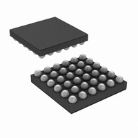
Package / Case
49-MicroSMDxt
Dc
07+
For Use With
LM49370RLEVAL - BOARD EVALUATION LM49370RL
Lead Free Status / RoHS Status
Lead free / RoHS Compliant
Other names
LM49370RLTR


www.national.com
Bits
2:0
5:3
12.38 GPIO CONFIGURATION REGISTER
This register is used to control the GPIOs and to control the digital signal routing when using the ADC and DAC to perform sample
rate conversion.
12.39 DAC PATH COMPENSATION FIR CONFIGURATION REGISTERS
To allow for compensation of roll off in the DAC and analog filter sections an FIR compensation filter is applied to the DAC input
data at the original sample rate. Since the DAC can operate at different over sampling ratios the FIR compensation filter is pro-
grammable. By default the filter applies approx 2dB of compensation at 20kHz. 5 taps is sufficient to allow passband equalization
and ripple cancellation to around +/0.01dB.
The filter can also be used for precise digital gain and simple tone controls although a DSP or CPU should be used for more
powerful tone control if required. As the FIR filter must always be phase linear, the coefficients are symmetrical. Coefficients C0,
C1, and C2 are programmable, C3 is equal to C1 and C4 is equal to C0. The maximum power of this filter must not exceed that
of the examples given below:
6
7
ADC_SRC_MODE If set, the ADC analog is disabled and the digital is enabled, using the resampler input.
DAC_SRC_MODE This does not have to be set to use DAC in SRC mode, but should be set if the user wishes to disable the
GPIO_1_SEL
GPIO_2_SEL
Field
This configures the GPIO_1 pin.
This configures the GPIO_2 pin.
DAC analog to save power.
GPIO_1_SEL
GPIO_2_SEL
000
001
010
011
100
101
110
111
000
001
010
011
100
101
110
111
2
2
2
2
2
2
2
2
2
2
2
2
2
2
2
2
TABLE 38. GPIO Control (0x1Fh)
56
Dig_Mic R Clock
Dig_Mic L Clock
Class D Enable
Class D Enable
Dig_Mic_Data
Does What?
Does What?
Description
AUX Enable
SPI_SDO
SPI_SDO
Output 0
Output 1
Output 0
Output 1
Disable
Disable
Read
Read
Direction
Direction
Output
Output
Output
Output
Output
Output
Output
Output
Output
Output
Output
Input
Input
Input
HiZ
HiZ
Related parts for LM49370RL/NOPB
Image
Part Number
Description
Manufacturer
Datasheet
Request
R

Part Number:
Description:
Audio Sub-system With An Ultra Low Emi, Spread Spectrum, Class D Loudspeaker Amplifier, A Dual-mode Stereo Headphone Amplifier, And A Dedicated Pcm Interface For Bluetooth Transceivers
Manufacturer:
National Semiconductor Corporation
Datasheet:

Part Number:
Description:
National Semiconductor [8-Bit D/A Converter]
Manufacturer:
National Semiconductor
Datasheet:
Part Number:
Description:
National Semiconductor [Media Coprocessor]
Manufacturer:
National Semiconductor
Datasheet:
Part Number:
Description:
Digitally Controlled Tone and Volume Circuit with Stereo Audio Power Amplifier, Microphone Preamp Stage and National 3D Sound
Manufacturer:
National Semiconductor
Datasheet:
Part Number:
Description:
Digitally Controlled Tone and Volume Circuit with Stereo Audio Power Amplifier, Microphone Preamp Stage and National 3D Sound
Manufacturer:
National Semiconductor
Datasheet:
Part Number:
Description:
AC97 Rev 2 Codec with Sample Rate Conversion and National 3D Sound
Manufacturer:
National Semiconductor
Part Number:
Description:
Manufacturer:
National Semiconductor
Datasheet:
Part Number:
Description:
Manufacturer:
National Semiconductor
Datasheet:
Part Number:
Description:
General Purpose, Low Voltage, Low Power, Rail-to-Rail Output Operational Amplifiers
Manufacturer:
National Semiconductor
Datasheet:
Part Number:
Description:
8-bit 20 MSPS flash A/D converter.
Manufacturer:
National Semiconductor
Datasheet:
Part Number:
Description:
Low Noise Quad Operational Amplifier
Manufacturer:
National Semiconductor
Datasheet:
Part Number:
Description:
Quad Differential Line Receivers
Manufacturer:
National Semiconductor
Datasheet:
Part Number:
Description:
Quad High Speed Trapezoidal? Bus Transceiver
Manufacturer:
National Semiconductor
Datasheet:
Part Number:
Description:
Dual Line Receiver
Manufacturer:
National Semiconductor
Datasheet: