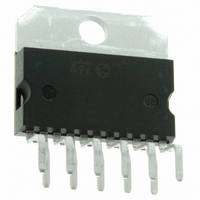
TDA1910HS STMicroelectronics, TDA1910HS Datasheet - Page 12

TDA1910HS
Manufacturer Part Number
TDA1910HS
Description
IC AMP AUD 10W MULTIWATT11 HORZ
Manufacturer
STMicroelectronics
Type
Class ABr
Datasheet
1.TDA1910HS.pdf
(15 pages)
Specifications of TDA1910HS
Output Type
1-Channel (Mono)
Max Output Power X Channels @ Load
17W x 1 @ 4 Ohm
Voltage - Supply
8 V ~ 30 V
Features
Depop, Mute, Thermal Protection
Mounting Type
Through Hole
Package / Case
Multiwatt-11 (Horizontal, Bent and Staggered Leads)
Operational Class
Class-AB
Audio Amplifier Output Configuration
1-Channel Mono
Output Power (typ)
17x1@4OhmW
Audio Amplifier Function
Speaker
Total Harmonic Distortion
0.2@8Ohm@7W%
Single Supply Voltage (typ)
9/12/15/18/24/28V
Dual Supply Voltage (typ)
Not RequiredV
Power Supply Requirement
Single
Power Dissipation
20W
Rail/rail I/o Type
No
Power Supply Rejection Ratio
60dB
Single Supply Voltage (min)
8V
Single Supply Voltage (max)
30V
Dual Supply Voltage (min)
Not RequiredV
Dual Supply Voltage (max)
Not RequiredV
Operating Temp Range
-40C to 150C
Operating Temperature Classification
Automotive
Mounting
Through Hole
Pin Count
11 +Tab
Package Type
MULTIWATT H
Lead Free Status / RoHS Status
Lead free / RoHS Compliant
Other names
497-8860-5
TDA1910HS
TDA1910HS
Available stocks
Company
Part Number
Manufacturer
Quantity
Price
THERMAL SHUT-DOWN
The presence of a thermal limiting circuit offers the
following advantages:
1) An overload on the output (even if it is perma-
2) The heatskink can have a smaller factor of
Figure 29. Output power and
dr ai n c urr en t vs.
temperature
MOUNTING INSTRUCTIONS
The power dissipated in the circuit must be re-
moved by adding an external heatsink.
Thanks to the Multiwatt® package attaching the
heatsink is very simple, a screw or a compression
TDA1910
12/15
nent), or an above limit ambient temperature
can be easily supported since the T
higher than 150 C.
safety compared with that of a conventional
case
Figure 30. Output power and
dra i n cu rre nt vs. case
temperature
j
cannot be
The maximum allowable power dissipation de-
pends upon the size of the external heatsink (i.e. its
thermal resistance); fig. 31 shows this dissipable
power as a function of ambient temperature for
different thermal resistance.
spring (clip) being sufficient. Between the heatsink
and the package it is better to insert a layer of silicon
grease, to optimize the thermal contact; no electri-
cal isolation is needed between the two surfaces.
circuit. There is no possibility of device damage
due to high junction temperature.
If for any reason, the junction temperature in-
creases up to 150 C, the thermal shut-down
simply reduces the power dissipation and the
current consumption.
Figure 31. Maximum allow able
power dissipation vs. ambient
temperature


