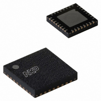
NE58633BS,115 NXP Semiconductors, NE58633BS,115 Datasheet - Page 16

NE58633BS,115
Manufacturer Part Number
NE58633BS,115
Description
IC AMP AUDIO .04W STER D 32HVQFN
Manufacturer
NXP Semiconductors
Type
Class Dr
Datasheet
1.NE58633BS157.pdf
(27 pages)
Specifications of NE58633BS,115
Output Type
Headphones, 2-Channel (Stereo)
Package / Case
32-VQFN Exposed Pad, 32-HVQFN, 32-SQFN, 32-DHVQFN
Max Output Power X Channels @ Load
40mW x 2 @ 16 Ohm
Voltage - Supply
0.9 V ~ 1.7 V
Features
Depop, Differential Inputs, Microphone, Mute, Short-Circuit Protection
Mounting Type
Surface Mount
Product
Class-D
Output Power
40 mW
Available Set Gain
100 dB
Common Mode Rejection Ratio (min)
30 dB
Thd Plus Noise
1 %
Operating Supply Voltage
0.9 V to 1.7 V
Supply Current
5 mA
Maximum Operating Temperature
+ 70 C
Mounting Style
SMD/SMT
Audio Load Resistance
32 Ohms
Input Offset Voltage
1 mV
Input Signal Type
Differential
Minimum Operating Temperature
0 C
Output Signal Type
Differential, Single
Supply Type
Single
Supply Voltage (max)
1.7 V
Supply Voltage (min)
0.9 V
Lead Free Status / RoHS Status
Lead free / RoHS Compliant
Other names
935283227115
NE58633BS-G
NE58633BS-G
NE58633BS-G
NE58633BS-G
NXP Semiconductors
NE58633_3
Product data sheet
10.4.2 Critical layout consideration and component selection
10.8.1 Basic concept
10.5 Mute
10.6 Internal reference, VREF pin
10.7 Power-on delay time and pop and click performance
10.8 Active Noise Reduction (ANR) concepts
The trace between pin BS and the switching inductor must be kept as short as possible.
The VBAT side of the boost switching inductor is decoupled by use of a low Equivalent
Series Resistance (ESR) 10 μF, 6 V capacitor. A power inductor with low ESR (typically
50 mΩ) should be used. The boost inductor must be 22 μH to ensure proper operation
over V
33 μF to 47 μF at the V
Mute may be invoked by directly grounding the pin with a momentary switch. The MUTE
pin is active LOW. The outputs are muted automatically when V
0.9 V. The MUTE pin is decoupled to ground with a 1 μF capacitor. The value of the MUTE
decoupling capacitor may be increased to keep outputs muted longer.
The internal reference is pinned out so it can be filtered with a capacitor to ground. The
recommended value is 1 μF to 10 μF. Ensure that the biasing time constant at pin VREF
does not exceed the power-on delay time or a pop-on click will heard.
Power-on delay time of typically 135 ms is imposed to allow the input biasing to power-up
and stabilize. This eliminates pop-on noise for most ANR filter networks. However,
specific ANR filter circuits have longer power-on delays. The MUTE decoupling may be
increased to keep outputs muted longer and eliminate pop-on noise.
Noise reduction headphones utilize Passive Noise Reduction (PNR) provided by the
passive noise reduction of the headphone acoustical plant alone. The amount of PNR is
greatest at the high frequencies and least at the low frequencies. The addition of Active
Noise Reduction (ANR) greatly increases the amount of noise reduction at low
frequencies. The combined effect of PNR and ANR provides noise reduction over an
appreciable hearing range.
an over-the-ear noise-cancelling FB headphone.
BAT
voltage. Pin B_IN is decoupled by use of a 1 μF capacitor directly at the pin with
Rev. 03 — 19 January 2010
bst
output at the Schottky diode.
Figure 16
Noise reduction class-D headphone driver amplifier
shows the combined effect of both PNR and ANR in
BAT
is less than or equal to
NE58633
© NXP B.V. 2010. All rights reserved.
16 of 27


