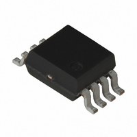
UPC3231GV-E1-A NEC, UPC3231GV-E1-A Datasheet

UPC3231GV-E1-A
Specifications of UPC3231GV-E1-A
Related parts for UPC3231GV-E1-A
UPC3231GV-E1-A Summary of contents
Page 1
GENERAL PURPOSE 5 V 100 MHz AGC AMPLIFIER DESCRIPTION µ The PC3231GV is a silicon monolithic IC designed for use as AGC amplifier for digital CATV, cable modem and digital terrestrial systems. This IC consists of gain control amplifier and ...
Page 2
... INTERNAL BLOCK DIAGRAM AND PIN CONNECTIONS INPUT1 2 INPUT2 AGC PRODUCT LINE- AGC AMPLIFIER MAX Part Number (mA) (dB) µ PC3217GV 23 53 µ PC3218GV 23 63 µ PC3219GV 36.5 42.5 µ PC3221GV 33 60 µ PC3231GV 36 65 Notes MHz MHz MHz MHz (Top View) 8 AGC AMP. ...
Page 3
... V AGC Recommended to use AGC voltage with externally resister (example: 1 kΩ). Ground pin. This pin should be connected to system ground with minimum inductance. Ground pattern on the board should be formed as wide as possible. Signal output pins of video amplifier. This pin should be coupled with capacitor for DC cut ...
Page 4
ABSOLUTE MAXIMUM RATINGS Parameter Symbol Supply Voltage V Gain Control Voltage Range V Power Dissipation P Storage Temperature T Note Mounted on double-sided copper-clad 50 × 50 × 1.6 mm epoxy glass PWB RECOMMENDED OPERATING RANGE Parameter Symbol Supply Voltage ...
Page 5
ELECTRICAL CHARACTERISTICS (T = +25° MHz Parameter Symbol DC Characteristics Circuit Current AGC Voltage High Level V AGC (H) AGC Voltage Low Level V AGC (L) RF Characteristics IF Input ...
Page 6
MEASUREMENT CIRCUIT 1 V µ Signal Note µ Generator 50 Ω µ kΩ µ AGC Note Balun Transformer: TOKO 617DB-1674 B4F (Double balanced type) MEASUREMENT CIRCUIT µ ...
Page 7
MEASUREMENT CIRCUIT 3 µ Ω 1 kΩ µ AGC MEASUREMENT CIRCUIT 4 (PRESSURE IMPROVEMENT RECOMMENDATION CIRCUIT) V µ Signal Note 100 pF Generator 50 Ω 100 pF 1 kΩ µ ...
Page 8
MEASUREMENT CIRCUIT 5 (PRESSURE IMPROVEMENT RECOMMENDATION CIRCUIT µ Note 100 pF 100 pF 1 kΩ µ AGC Noise Source Note Balun Transformer: TOKO 617DB-1674 B4F (Double balanced type) MEASUREMENT CIRCUIT 6 (PRESSURE IMPROVEMENT ...
Page 9
ILLUSTRATION OF THE TEST CIRCUIT ASSEMBLED ON EVALUATION BOARD (MEASUREMENT CIRCUIT 1) IN1 Note Balun Transformer Remarks 1. Back side: GND pattern 2. Au plated on pattern 3. : Through hole V CC 200 Ω µ Note µ ...
Page 10
TYPICAL CHARACTERISTICS (T CIRCUIT CURRENT vs. SUPPLY VOLTAGE 40 No input signal Supply Voltage V (V) CC AGC PIN CURRENT vs. GAIN CONTROL VOLTAGE RANGE 80 No ...
Page 11
OUTPUT POWER vs. INPUT POWER MHz V = 3.0 V AGC –5 –10 –15 V –20 –90 –80 –70 –60 –50 –40 –30 –20 Input Power P (dBm) in OUTPUT POWER vs. INPUT ...
Page 12
NOISE FIGURE vs. GAIN CONTROL VOLTAGE RANGE MHz 1.0 1.5 2.0 2.5 3.0 Gain Control Voltage Range V NOISE FIGURE vs. GAIN REDUCTION MHz ...
Page 13
OUTPUT POWER, IM vs. INPUT POWER 4 5 out –10 – –30 –40 –50 –60 V – MHz MHz –80 ...
Page 14
S-PARAMETERS (T = +25° −FREQUENCY S 11 −FREQUENCY 5 AGC MHz MHz Data Sheet PU10658EJ01V0DS µ PC3231GV 223.93 Ω –506.44 ...
Page 15
PACKAGE DIMENSIONS 8-PIN PLASTIC SSOP (4.45 mm (175)) (UNIT: mm 2.9±0.1 1.8 MAX. 1.5±0.1 0.65 +0.10 0.3 0.10 –0.05 0.1±0.1 5 detail of lead end 4 4.94±0.2 3.2±0.1 0.575 MAX. 0.5±0.2 M +0.10 0.15 –0.05 Data Sheet PU10658EJ01V0DS ...
Page 16
... Observe precautions for handling because of electro-static sensitive devices. (2) Form a ground pattern as widely as possible to minimize ground impedance (to prevent undesired oscillation). All the ground pins must be connected together with wide ground pattern to decrease impedance difference. (3) The bypass capacitor should be attached to V RECOMMENDED SOLDERING CONDITIONS This product should be soldered and mounted under the following recommended conditions ...
Page 17
... NEC Electronics does not assume any liability for infringement of patents, copyrights or other intellectual property rights of third parties by or arising from the use of NEC Electronics products listed in this document or any other liability arising from the use of such products. No license, express, implied or otherwise, is granted under any patents, copyrights or other intellectual property rights of NEC Electronics or others. • ...
Page 18
Subject: Compliance with EU Directives CEL certifies, to its knowledge, that semiconductor and laser products detailed below are compliant with the requirements of European Union (EU) Directive 2002/95/EC Restriction on Use of Hazardous Substances in electrical and electronic equipment (RoHS) ...


