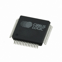
CS44800-CQZR Cirrus Logic Inc, CS44800-CQZR Datasheet - Page 52

CS44800-CQZR
Manufacturer Part Number
CS44800-CQZR
Description
IC AMP CTLR DGTL 8CH 64-LQFP
Manufacturer
Cirrus Logic Inc
Type
Amplifierr
Datasheet
1.CS44800-CQZR.pdf
(80 pages)
Specifications of CS44800-CQZR
Package / Case
64-LQFP
Applications
Automotive Audio
Mounting Type
Surface Mount
Product
Class-D
Operating Supply Voltage
2.5 V
Supply Current
150 mA
Maximum Operating Temperature
+ 70 C
Mounting Style
SMD/SMT
Minimum Operating Temperature
- 10 C
Supply Type
Digital
Supply Voltage (max)
2.62 V
Supply Voltage (min)
2.37 V
Lead Free Status / RoHS Status
Lead free / RoHS Compliant
For Use With
598-1532 - BOARD EVAL FOR CS44800 PWM CTRL
Lead Free Status / RoHS Status
Lead free / RoHS Compliant, Lead free / RoHS Compliant
52
7.3.5
7.3.6
7.4
7.4.1
PDN_PWMB4
7
PWM Channel Power Down Control (address 03h)
Power Down Output Mode (PDN_OUTPUT_MODE)
Default = 0
0 - PWM Outputs are driven low during power down
1 - PWM Outputs are driven to the inactive state during power down
Function:
This bit is used to select the power-down state of the PWM output signals. When set to 0, each channel
which has been powered down, following the ramp-down cycle if enabled, will drive the output signals,
PWMOUTxx+ and PWMOUTxx-, low.
When set to 1, each channel which has been powered down, following the ramp-down cycle if enabled,
will drive the output signals to the inactive state. PWMOUTxx+ is driven low and PWMOUTxx- is driven
high.
Power Down (PDN)
Default = 1
0 - Normal Operation
1 - Power down
Function:
The entire device will enter a low-power state when this function is enabled, and the contents of the control
registers are retained in this mode. The power-down bit defaults to ‘enabled’ on power-up and must be
disabled before normal operation can occur.
Power Down PWM Channels (PDN_PWMB
Default = 11111111
0 - Normal Operation
1 - Power down PWM channel
Function:
The specific PWM channel is in the power-down state. All processing is halted for the specific channel,
but does not alter the setup or delay register values. The PWM output signals are driven to the appropriate
logic level as defined by the Power-Down Output Mode bit, PDN_OUTPUT_MODE. When set to normal
operation, the specific channel will power up according to the state of the RAMP[1:0] bits and the channel
output configuration selected. When transitioning from normal operation to power down, the specific chan-
nel will power down according to the state of the RAMP[1:0] bits and the channel output configuration se-
lected. Ramp control is found in
PDN_PWMA4
6
PDN_PWMB3
5
“Ramp Configuration (address 05h)” on page
PDN_PWMA3
4
PDN_PWMB2
3
4
:PDN_PWMA1)
PDN_PWMA2
2
PDN_PWMB1
54.
1
CS44800
PDN_PWMA1
DS632F1
0


