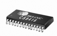
CS8416-CNZ Cirrus Logic Inc, CS8416-CNZ Datasheet - Page 41

CS8416-CNZ
Manufacturer Part Number
CS8416-CNZ
Description
IC RCVR DGTL 192KHZ 28QFN COMM
Manufacturer
Cirrus Logic Inc
Type
Digital Audio Interface Receiverr
Datasheet
1.CS8416-CZZ.pdf
(60 pages)
Specifications of CS8416-CNZ
Applications
Digital Audio
Mounting Type
Surface Mount
Package / Case
28-QFN
Audio Control Type
Digital
Control Interface
I2C, SPI
Control / Process Application
AV & DVD Receivers, CD-R, Digital Mixing Consoles
Supply Voltage Range
3.13V To 5.25V, 3.13V To 3.46V
Lead Free Status / RoHS Status
Lead free / RoHS Compliant
For Use With
598-1017 - BOARD EVAL FOR CS8416 RCVR
Lead Free Status / RoHS Status
Lead free / RoHS Compliant, Lead free / RoHS Compliant
Other names
598-1723
DS578F3
14.8
14.9
14.10 Interrupt Mode MSB (08h) and Interrupt Mode LSB(09h)
7
0
7
0
7
0
0
SOLRPOL - OLRCK clock polarity
Default = ‘0’
0 - SDOUT data is valid for the left channel when OLRCK is high.
1 - SDOUT data is valid for the right channel when OLRCK is high.
Receiver Error Mask (06h)
The bits in this register serve as masks for the corresponding bits of the Receiver Error Register. If a mask
bit is set to 1, the error is unmasked, meaning that its occurrence will appear in the receiver error register,
will affect RERR, will affect the RERR interrupt, and will affect the current audio sample according to the
status of the HOLD bit. If a mask bit is set to 0, the error is masked, meaning that its occurrence will not
appear in the receiver error register, will not affect the RERR pin, will not affect the RERR interrupt, and will
not affect the current audio sample. The CCRC and QCRC bits behave differently from the other bits: they
do not affect the current audio sample even when unmasked. This register defaults to 00h.
Interrupt Mask (07h)
The bits of this register serve as a mask for the Interrupt Status register. If a mask bit is set to 1, the error
is unmasked, meaning that its occurrence will affect the INT pin and the status register. If a mask bit is set
to 0, the error is masked, meaning that its occurrence will not affect the internal INT signal or the status reg-
ister. The bit positions align with the corresponding bits in Interrupt Status register. This register defaults to
00h.
The INT signal may be selected to output on the GPO pins. See
The two Interrupt Mode registers form a 2-bit code for each Interrupt Status register function. There are
three ways to set the INT pin active in accordance with the interrupt condition. In the Rising edge active
mode, the INT pin becomes active on the arrival of the interrupt condition. In the Falling edge active mode,
the INT pin becomes active on the removal of the interrupt condition. In Level active mode, the INT interrupt
pin becomes active during the interrupt condition. Be aware that the active level (Active High or Low) only
depends on the INT[1:0] bits. These registers default to 00h.
00 - Rising edge active
01 - Falling edge active
10 - Level active
11 - Reserved
QCRCM
PCCHM
PCCH1
PCCH0
6
6
6
CCRCM
OSLIPM
OSLIP1
OSLIP0
5
5
5
UNLOCKM
DETCM
DETC1
DETC0
4
4
4
CCHM
CCH1
CCH0
VM
3
3
3
“General Purpose Outputs” on page
RERRM
CONFM
RERR1
RERR0
2
2
2
QCHM
QCH1
QCH0
BIPM
1
1
1
CS8416
PARM
FCHM
FCH1
FCH0
0
0
0
29.
41


