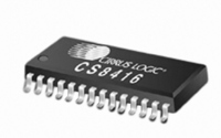
CS8416-CNZ Cirrus Logic Inc, CS8416-CNZ Datasheet - Page 51

CS8416-CNZ
Manufacturer Part Number
CS8416-CNZ
Description
IC RCVR DGTL 192KHZ 28QFN COMM
Manufacturer
Cirrus Logic Inc
Type
Digital Audio Interface Receiverr
Datasheet
1.CS8416-CZZ.pdf
(60 pages)
Specifications of CS8416-CNZ
Applications
Digital Audio
Mounting Type
Surface Mount
Package / Case
28-QFN
Audio Control Type
Digital
Control Interface
I2C, SPI
Control / Process Application
AV & DVD Receivers, CD-R, Digital Mixing Consoles
Supply Voltage Range
3.13V To 5.25V, 3.13V To 3.46V
Lead Free Status / RoHS Status
Lead free / RoHS Compliant
For Use With
598-1017 - BOARD EVAL FOR CS8416 RCVR
Lead Free Status / RoHS Status
Lead free / RoHS Compliant, Lead free / RoHS Compliant
Other names
598-1723
DS578F3
17.CHANNEL STATUS BUFFER MANAGEMENT
17.1
17.2
17.2.1 Serial Copy Management System (SCMS)
AES3 Channel Status (C) Bit Management
The CS8416 contains sufficient RAM to store the first 5 bytes of C data for both A and B channels
(5 x 2 x 8 = 80 bits). The user may read from this buffer’s RAM through the control port.
The buffering scheme involves two buffers, named D and E, as shown in
represents the first bit in the serial C data stream. For example, the MSB of byte 0 (which is at control port
address 19h) is the consumer/professional bit for channel status block A.
The first buffer (D) accepts incoming C data from the AES receiver. The 2nd buffer (E) accepts entire blocks
of data from the D buffer. The E buffer is also accessible from the control port, allowing reading of the first
five bytes of C data.
The complete C data may be obtained through the C pin in Hardware Mode and through one of the GPO
pins in Software Mode. The C data is serially shifted out of the CS8416 clocked by the rising and falling
edges of OLRCK.
Accessing the E Buffer
The user can monitor the incoming data by reading the E buffer, which is mapped into the register space of
the CS8416, through the control port.
The user can configure the interrupt enable register to cause interrupts to occur whenever D to E buffer
transfers occur. This allows determination of the allowable time periods to interact with the E buffer.
Also provided is a D to E inhibit bit in the Control2 register (02h). This may be used whenever “long” control
port interactions are occurring or for debugging purposes.
A flowchart for reading the E buffer is shown in
there is a substantial time interval until the next D to E transfer (approximately 192 frames worth of time).
This is usually enough time to access the E data without having to inhibit the next transfer.
In Software Mode, the CS8416 allows read access to all the channel status bits. For consumer mode
SCMS compliance, the host microcontroller needs to read and interpret the Category Code, Copy bit and
L bit appropriately.
In Hardware Mode, the SCMS protocol can be followed by either using the COPY and ORIG output pins,
or by using the C bit serial output pin. These options are documented in
page
46.
Figure
22. Since a D to E interrupt occurs just after reading,
Figure
Section 15. “Hardware Mode” on
21. The MSB of each byte
CS8416
51


