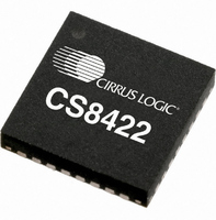
CS8422-CNZ Cirrus Logic Inc, CS8422-CNZ Datasheet - Page 60

CS8422-CNZ
Manufacturer Part Number
CS8422-CNZ
Description
IC SAMPLE RATE CONVERTER 32QFN
Manufacturer
Cirrus Logic Inc
Type
Sample Rate Converterr
Datasheet
1.CS8422-CNZ.pdf
(82 pages)
Specifications of CS8422-CNZ
Package / Case
32-QFN
Applications
Digital Audio
Mounting Type
Surface Mount
Maximum Operating Temperature
+ 125 C
Minimum Operating Temperature
- 55 C
Mounting Style
SMD/SMT
Package
32QFN
Operating Temperature
-55 to 125 °C
Audio Control Type
Sample Rate Converter
Control Interface
I2C, SPI
Supply Voltage Range
1.71V To 5.25V
Operating Temperature Range
-40°C To +85°C
Audio Ic Case Style
QFN
No. Of Pins
32
Rohs Compliant
Yes
Lead Free Status / RoHS Status
Lead free / RoHS Compliant
For Use With
598-1568 - BOARD EVAL FOR CS8422 RCVR
Lead Free Status / Rohs Status
Lead free / RoHS Compliant
Other names
598-1732
Available stocks
Company
Part Number
Manufacturer
Quantity
Price
Company:
Part Number:
CS8422-CNZ
Manufacturer:
CIRRUS
Quantity:
99
Part Number:
CS8422-CNZ
Manufacturer:
CIRRUS
Quantity:
20 000
Part Number:
CS8422-CNZR
Manufacturer:
CIRRUS
Quantity:
20 000
60
11.21 PLL Status (15h)
RX_ACTIVE
7
DETC - D to E C-buffer transfer interrupt.
CCH - C-Data change.
RERR - A receiver error has occurred.
QCH – A new block of Q-subcode is available for reading.
FCH – Format Change
SRC_UNLOCK - SRC Unlock condition.
RX_ACTIVE - Receiver Active
ISCLK_ACTIVE- ISCLK Active
PLL_LOCK -
96KHZ – Indicates the frequency range of the sample rate of incoming AES3 data (Fsi). If Fsi 49 kHz or
Fsi 120 kHz, this bit will output a “0”. If 60 kHz Fsi 98 kHz, this bit will output a “1”. Otherwise the output
is indeterminate.
192KHZ – Indicates the frequency range of the sample rate of incoming AES3 data (Fsi). If Fsi 98 kHz,
this bit will output a “0”. If Fsi 120 kHz, this bit will output a “1”. Otherwise the output is indeterminate.
Indicates the completion of a D to E C-buffer transfer. See “Channel Status Buffer Management” on page
53.
Indicates that the current 10 bytes of channel status is different from the previous 10 bytes. (5 bytes per
channel)
The Receiver Error register may be read to determine the nature of the error which caused the interrupt.
The data must be read within 588 AES3 frames after the interrupt occurs to avoid corruption of the data
by the next block.
Goes high when the PCM, IEC61937, DTS_LD, DTS_CD, or DGTL_SIL bits in the Format Detect Status
register transition from 0 to 1. When these bits in the Format Detect Status register transition from 1 to 0,
an interrupt will not be generated.
Indicates that the SRC has lost the ability to output valid data
This bit is a level-signal version of the ACTIVE bit in register 13h.
0 - There is no toggling on the ISCLK pin, or the frequency of toggling is less than 36 kHz on the ISCLK
pin.
1 - There is toggling at a frequency of at least 1.536 MHz on the ISCLK pin.
0 - The PLL has not achieved lock.
1 - The PLL, driven by either an AES3 or ISCLK input, has achieved lock.
ACTIVE
ISCLK
6
PLL_LOCK
5
96KHZ
4
192KHZ
3
Reserved
2
Reserved
1
CS8422
Reserved
DS692F1
0


