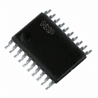
74LVC245APW,118 NXP Semiconductors, 74LVC245APW,118 Datasheet - Page 9

74LVC245APW,118
Manufacturer Part Number
74LVC245APW,118
Description
IC TRANSCVR TRI-ST 8BIT 20TSSOP
Manufacturer
NXP Semiconductors
Series
74LVCr
Datasheet
1.74LVC245APW118.pdf
(17 pages)
Specifications of 74LVC245APW,118
Logic Type
Transceiver, Non-Inverting
Package / Case
20-TSSOP
Number Of Elements
1
Number Of Bits Per Element
8
Current - Output High, Low
24mA, 24mA
Voltage - Supply
2.7 V ~ 3.6 V
Operating Temperature
-40°C ~ 125°C
Mounting Type
Surface Mount
Logic Family
LVC
Number Of Channels Per Chip
8
Input Level
LVTTL
Output Level
LVTTL
Output Type
3-State
High Level Output Current
- 24 mA
Low Level Output Current
24 mA
Propagation Delay Time
17 ns
Supply Voltage (max)
3.6 V
Supply Voltage (min)
1.2 V
Maximum Operating Temperature
+ 125 C
Function
Bus Transceiver
Input Bias Current (max)
40 uA
Minimum Operating Temperature
- 40 C
Mounting Style
SMD/SMT
Polarity
Non-Inverting
Number Of Circuits
1
Operating Supply Voltage (typ)
1.8/2.5/3.3V
Number Of Elements
1
Number Of Channels
8
Input Logic Level
LVTTL
Output Logic Level
LVTTL
Package Type
TSSOP
Logical Function
Bus Transceiver
Operating Supply Voltage (min)
1.2V
Operating Supply Voltage (max)
3.6V
Quiescent Current (typ)
100nA
Technology
CMOS
Operating Temp Range
-40C to 125C
Operating Temperature Classification
Automotive
Mounting
Surface Mount
Pin Count
20
Lead Free Status / RoHS Status
Lead free / RoHS Compliant
Lead Free Status / RoHS Status
Lead free / RoHS Compliant, Lead free / RoHS Compliant
Other names
568-2301-2
74LVC245APW-T
935211540118
74LVC245APW-T
935211540118
Available stocks
Company
Part Number
Manufacturer
Quantity
Price
Company:
Part Number:
74LVC245APW,118
Manufacturer:
NXP Semiconductors
Quantity:
1 950
NXP Semiconductors
Table 9.
[1]
74LVC_LVCH245A_5
Product data sheet
Supply voltage
1.2 V
2.7 V
3.0 V to 3.6 V
Fig 7.
The circuit performs better when R
Test data is given in
Definitions for test circuit:
R
C
R
V
Test circuit for measuring switching times
EXT
L
L
T
Test data
= Load resistance.
= Load capacitance including jig and probe capacitance.
= Termination resistance should be equal to output impedance Z
= External voltage for measuring switching times.
Input
V
V
2.7 V
2.7 V
I
CC
Table
9.
negative
L
positive
= 1 k .
pulse
pulse
0 V
0 V
V
V
t
r
I
I
, t
2.5 ns
2.5 ns
2.5 ns
G
f
90 %
10 %
Rev. 05 — 25 August 2009
V
I
t
t
f
r
V
V
M
M
10 %
90 %
Load
C
50 pF
50 pF
50 pF
R T
L
V
DUT
CC
74LVC245A; 74LVCH245A
t
t
W
W
V
O
R
500
500
500
o
L
of the pulse generator.
C L
[1]
V
V
M
M
001aae331
t
t
V
r
f
EXT
R L
R L
V
t
open
open
open
PLH
EXT
, t
Octal bus transceiver; 3-state
PHL
t
2
2
2
PLZ
V
V
V
, t
CC
CC
CC
PZL
© NXP B.V. 2009. All rights reserved.
t
GND
GND
GND
PHZ
, t
PZH
9 of 17


