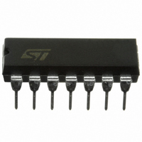
M74HCT74B1R STMicroelectronics, M74HCT74B1R Datasheet - Page 4

M74HCT74B1R
Manufacturer Part Number
M74HCT74B1R
Description
IC FLIP/FLOP DUAL D TYPE 14-DIP
Manufacturer
STMicroelectronics
Series
74HCTr
Type
D-Typer
Datasheet
1.M74HCT74RM13TR.pdf
(10 pages)
Specifications of M74HCT74B1R
Function
Set(Preset) and Reset
Output Type
Differential
Number Of Elements
2
Number Of Bits Per Element
1
Frequency - Clock
48MHz
Delay Time - Propagation
21ns
Trigger Type
Positive Edge
Current - Output High, Low
4mA, 4mA
Voltage - Supply
4.5 V ~ 5.5 V
Operating Temperature
-55°C ~ 125°C
Mounting Type
Through Hole
Package / Case
14-DIP (0.300", 7.62mm)
Logic Family
HCT
Technology
CMOS
Number Of Bits
2
Number Of Elements
2
Clock-edge Trigger Type
Positive-Edge
Polarity
Invert/Non-Invert
Operating Supply Voltage (typ)
5V
Package Type
PDIP
Propagation Delay Time
50ns
Low Level Output Current
4mA
High Level Output Current
-4mA
Frequency (max)
18MHz
Operating Supply Voltage (min)
4.5V
Operating Supply Voltage (max)
5.5V
Operating Temp Range
-55C to 125C
Operating Temperature Classification
Military
Mounting
Through Hole
Pin Count
14
Number Of Circuits
2
Logic Type
D-Type Flip-Flop
Input Type
Single-Ended
Supply Voltage (max)
5.5 V
Maximum Operating Temperature
+ 125 C
Mounting Style
Through Hole
Minimum Operating Temperature
- 55 C
Supply Voltage (min)
4.5 V
Lead Free Status / RoHS Status
Lead free / RoHS Compliant
Other names
497-1922-5
M74HCT74
AC ELECTRICAL CHARACTERISTICS (C
CAPACITIVE CHARACTERISTICS
1) C
load. (Refer to Test Circuit). Average operating current can be obtained by the following equation. I
FLOP)
4/10
t
t
t
Symbol
Symbol
TLH
PLH
PLH
t
t
f
t
t
C
PD
MAX
W(H)
W(L)
W(L)
REM
C
t
t
PD
s
h
IN
t
t
t
is defined as the value of the IC’s internal equivalent capacitance which is calculated from the operating current consumption without
THL
PHL
PHL
Output Transition
Time
Propagation Delay
Time (CLOCK-Q)
Propagation Delay
Time (CL,PR - Q,Q)
Maximum Clock
Frequency
Minimum Pulse
Width (CLOCK)
Minimum Pulse
Width (CLR, PR)
Minimum Set-Up
Time
Minimum Hold
Time
Minimum Removal
Time (CLR, PR to
CLOCK)
Input Capacitance
Power Dissipation
Capacitance (note
1)
Parameter
Parameter
V
V
(V)
4.5
4.5
4.5
4.5
4.5
4.5
4.5
4.5
4.5
(V)
CC
CC
Test Condition
Test Condition
L
= 50 pF, Input t
Min.
Min.
27
T
T
A
A
r
Typ.
Typ.
= 25°C
= 25°C
21
18
48
32
= t
8
6
8
7
1
5
f
= 6ns)
Max.
Max.
15
33
30
15
15
15
10
0
5
Value
Value
CC(opr)
-40 to 85°C
Min.
-40 to 85°C
Min.
22
5
= C
Max.
Max.
19
41
38
19
19
19
10
PD
0
6
x V
CC
-55 to 125°C
-55 to 125°C
Min.
Min.
18
5
x f
IN
+ I
Max.
Max.
CC
22
50
45
23
23
23
10
0
8
/2 (per FLIP/
MHz
Unit
Unit
pF
pF
ns
ns
ns
ns
ns
ns
ns
ns


