74AUP1Z125GM,115 NXP Semiconductors, 74AUP1Z125GM,115 Datasheet
74AUP1Z125GM,115
Specifications of 74AUP1Z125GM,115
74AUP1Z125GM-G
935280525115


Related parts for 74AUP1Z125GM,115


74AUP1Z125GM,115 Summary of contents
Page 1
Low-power X-tal driver with enable and internal resistor; 3-state Rev. 3 — 9 September 2010 1. General description The 74AUP1Z125 combines the functions of the 74AUP1GU04 and 74AUP1G125 with enable circuitry and an internal bias resistor to provide a ...
Page 2
... NXP Semiconductors 3. Ordering information Table 1. Ordering information Type number Package Temperature range Name −40 °C to +125 °C 74AUP1Z125GW −40 °C to +125 °C 74AUP1Z125GM −40 °C to +125 °C 74AUP1Z125GF −40 °C to +125 °C 74AUP1Z125GN −40 °C to +125 °C 74AUP1Z125GS 4. Marking Table 2. Marking ...
Page 3
... NXP Semiconductors 6. Pinning information 6.1 Pinning 74AUP1Z125 GND 001aaf142 Fig 2. Pin configuration SOT363 6.2 Pin description Table 3. Pin description Symbol Pin EN 1 GND Functional description [1] Table 4. Function table Input [ HIGH voltage level LOW voltage level high-impedance OFF-state. 74AUP1Z125 Product data sheet Low-power X-tal driver with enable and internal resistor ...
Page 4
... NXP Semiconductors 8. Limiting values Table 5. Limiting values In accordance with the Absolute Maximum Rating System (IEC 60134). Voltages are referenced to GND (ground = 0 V). Symbol Parameter V supply voltage CC I input clamping current IK V input voltage I I output clamping current OK V output voltage O I output current ...
Page 5
... NXP Semiconductors 10. Static characteristics Table 7. Static characteristics At recommended operating conditions; voltages are referenced to GND (ground = 0 V). Symbol Parameter = 25 °C T amb V HIGH-level input voltage IH V LOW-level input voltage IL V HIGH-level output voltage OH 74AUP1Z125 Product data sheet Low-power X-tal driver with enable and internal resistor; 3-state ...
Page 6
... NXP Semiconductors Table 7. Static characteristics At recommended operating conditions; voltages are referenced to GND (ground = 0 V). Symbol Parameter V LOW-level output voltage OL I input leakage current I I pull-up current pu I OFF-state output current OZ I power-off leakage current OFF ΔI additional power-off OFF leakage current ...
Page 7
... NXP Semiconductors Table 7. Static characteristics At recommended operating conditions; voltages are referenced to GND (ground = 0 V). Symbol Parameter C output capacitance O g forward transconductance fs R bias resistance bias = −40 °C to +85 °C T amb V HIGH-level input voltage IH V LOW-level input voltage IL 74AUP1Z125 Product data sheet Low-power X-tal driver with enable and internal resistor ...
Page 8
... NXP Semiconductors Table 7. Static characteristics At recommended operating conditions; voltages are referenced to GND (ground = 0 V). Symbol Parameter V HIGH-level output voltage OH V LOW-level output voltage OL 74AUP1Z125 Product data sheet Low-power X-tal driver with enable and internal resistor; 3-state …continued Conditions Y output input = −20 μ ...
Page 9
... NXP Semiconductors Table 7. Static characteristics At recommended operating conditions; voltages are referenced to GND (ground = 0 V). Symbol Parameter I input leakage current I I pull-up current pu I OFF-state output current OZ I power-off leakage current OFF ΔI additional power-off OFF leakage current I supply current CC ΔI additional supply current ...
Page 10
... NXP Semiconductors Table 7. Static characteristics At recommended operating conditions; voltages are referenced to GND (ground = 0 V). Symbol Parameter = −40 °C to +125 °C T amb V HIGH-level input voltage IH V LOW-level input voltage IL V HIGH-level output voltage OH 74AUP1Z125 Product data sheet Low-power X-tal driver with enable and internal resistor; 3-state … ...
Page 11
... NXP Semiconductors Table 7. Static characteristics At recommended operating conditions; voltages are referenced to GND (ground = 0 V). Symbol Parameter V LOW-level output voltage OL I input leakage current I I pull-up current pu I OFF-state output current OZ I power-off leakage current OFF ΔI additional power-off OFF leakage current ...
Page 12
... NXP Semiconductors Table 7. Static characteristics At recommended operating conditions; voltages are referenced to GND (ground = 0 V). Symbol Parameter g forward transconductance fs R bias resistance bias [1] Only for output Y and input EN. V – ----------------- - bias I I Fig 5. Test circuit for measuring bias resistance 74AUP1Z125 Product data sheet Low-power X-tal driver with enable and internal resistor ...
Page 13
... NXP Semiconductors ( kHz MHz MHz. i Fig 6. Typical bias resistance versus supply voltage 74AUP1Z125 Product data sheet Low-power X-tal driver with enable and internal resistor; 3-state 20 R bias (MΩ (2) 4 (3) 0 1.0 1.5 2.0 2.5 All information provided in this document is subject to legal disclaimers. ...
Page 14
... NXP Semiconductors 11. Dynamic characteristics Table 8. Dynamic characteristics Voltages are referenced to GND (ground = 0 V); for test circuit see Symbol Parameter Conditions propagation delay X1 to X2; see see enable time see disable time see dis 74AUP1Z125 Product data sheet Low-power X-tal driver with enable and internal resistor; 3-state ...
Page 15
... NXP Semiconductors Table 8. Dynamic characteristics Voltages are referenced to GND (ground = 0 V); for test circuit see Symbol Parameter Conditions propagation delay X1 to X2; see see enable time see disable time see dis 74AUP1Z125 Product data sheet Low-power X-tal driver with enable and internal resistor; 3-state … ...
Page 16
... NXP Semiconductors Table 8. Dynamic characteristics Voltages are referenced to GND (ground = 0 V); for test circuit see Symbol Parameter Conditions propagation delay X1 to X2; see see enable time see disable time see dis 74AUP1Z125 Product data sheet Low-power X-tal driver with enable and internal resistor; 3-state … ...
Page 17
... NXP Semiconductors Table 8. Dynamic characteristics Voltages are referenced to GND (ground = 0 V); for test circuit see Symbol Parameter Conditions propagation delay X1 to X2; see see enable time see disable time see dis 74AUP1Z125 Product data sheet Low-power X-tal driver with enable and internal resistor; 3-state … ...
Page 18
... NXP Semiconductors Table 8. Dynamic characteristics Voltages are referenced to GND (ground = 0 V); for test circuit see Symbol Parameter Conditions pF and power dissipation MHz GND capacitance [1] All typical values are measured at nominal V [ the same as t and PLH PHL [ the same as t and t ...
Page 19
... NXP Semiconductors 12. Waveforms Measurement points are given in Logic levels: V and Fig 7. The input (X1) to output (X2, Y) propagation delays Table 9. Measurement points Supply voltage Output 0.5 × input Y output LOW-to-OFF OFF-to-LOW Y output HIGH-to-OFF OFF-to-HIGH Measurement points are given in Logic levels: V and V ...
Page 20
... NXP Semiconductors Test data is given in Table Definitions for test circuit Load resistance Load capacitance including jig and probe capacitance Termination resistance should be equal to the output impedance External voltage for measuring switching times. EXT Fig 9. Test circuit for measuring switching times Table 11. ...
Page 21
... NXP Semiconductors 13. Application information Crystal controlled oscillator circuits are widely used in clock pulse generators because of their excellent frequency stability and wide operating frequency range. The use of the 74AUP1Z125 provides the additional advantages of low power dissipation, stable operation over a wide range of frequency and temperature and a very small footprint. This application information describes crystal characteristics, design and testing of crystal oscillator circuits based on the 74AUP1Z125 ...
Page 22
... NXP Semiconductors (1) (a) = resonance (2) (b) = anti-resonance (3) (c) = load resonance Fig 13. Reactance and resistance characteristics of a crystal 13.1.1 Design Figure 14 circuit is basically a Pierce oscillator circuit in which the crystal is operating at its fundamental frequency and is tuned by the parallel load capacitance are in series with the crystal. They should be approximately equal. R ...
Page 23
... NXP Semiconductors Fig 14. Crystal oscillator configuration 13.1.2 Testing After the calculations are performed for a particular crystal, the oscillator circuit should be tested. The following simple checks will verify the prototype design of a crystal controlled oscillator circuit. Perform them after laying out the board: • ...
Page 24
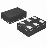
... NXP Semiconductors 14. Package outline Plastic surface-mounted package; 6 leads y 6 pin 1 index DIMENSIONS (mm are the original dimensions UNIT max 1.1 0.30 0.25 mm 0.1 0.8 0.20 0.10 OUTLINE VERSION IEC SOT363 Fig 15. Package outline SOT363 (SC-88) 74AUP1Z125 Product data sheet Low-power X-tal driver with enable and internal resistor; 3-state ...
Page 25
... NXP Semiconductors XSON6: plastic extremely thin small outline package; no leads; 6 terminals; body 1 x 1. 6× (2) terminal 1 index area DIMENSIONS (mm are the original dimensions) ( UNIT b D max max 0.25 1.5 mm 0.5 0.04 0.17 1.4 Notes 1. Including plating thickness. 2. Can be visible in some manufacturing processes. ...
Page 26
... NXP Semiconductors XSON6: plastic extremely thin small outline package; no leads; 6 terminals; body 0 6× (1) terminal 1 index area DIMENSIONS (mm are the original dimensions UNIT b D max max 0.20 1.05 mm 0.5 0.04 0.12 0.95 Note 1. Can be visible in some manufacturing processes. OUTLINE VERSION IEC SOT891 Fig 17 ...
Page 27
... NXP Semiconductors XSON6: extremely thin small outline package; no leads; 6 terminals; body 0.9 x 1 (6×) terminal 1 index area Dimensions (1) Unit max 0.35 0.04 0.20 0.95 mm nom 0.15 0.90 min 0.12 0.85 Note 1. Including plating thickness. 2. Visible depending upon used manufacturing technology. ...
Page 28
... NXP Semiconductors XSON6: extremely thin small outline package; no leads; 6 terminals; body 1.0 x 1 (6×) terminal 1 index area Dimensions (1) Unit max 0.35 0.04 0.20 1.05 mm nom 0.15 1.00 min 0.12 0.95 Note 1. Including plating thickness. 2. Visible depending upon used manufacturing technology. ...
Page 29
... NXP Semiconductors 15. Abbreviations Table 12. Abbreviations Acronym Description CDM Charged Device Model DUT Device Under Test ESD ElectroStatic Discharge HBM Human Body Model MM Machine Model 16. Revision history Table 13. Revision history Document ID Release date 74AUP1Z125 v.3 20100909 • Modifications: Added type number 74AUP1Z125GN (SOT1115/XSON6 package). ...
Page 30
... In no event shall NXP Semiconductors be liable for any indirect, incidental, punitive, special or consequential damages (including - without limitation - lost profits, lost savings, business interruption, costs related to the removal or ...
Page 31
... NXP Semiconductors Export control — This document as well as the item(s) described herein may be subject to export control regulations. Export might require a prior authorization from national authorities. 18. Contact information For more information, please visit: For sales office addresses, please send an email to: 74AUP1Z125 Product data sheet Low-power X-tal driver with enable and internal resistor ...
Page 32
... NXP Semiconductors 19. Contents 1 General description . . . . . . . . . . . . . . . . . . . . . . 1 2 Features and benefits . . . . . . . . . . . . . . . . . . . . 1 3 Ordering information . . . . . . . . . . . . . . . . . . . . . 2 4 Marking . . . . . . . . . . . . . . . . . . . . . . . . . . . . . . . . 2 5 Functional diagram . . . . . . . . . . . . . . . . . . . . . . 2 6 Pinning information . . . . . . . . . . . . . . . . . . . . . . 3 6.1 Pinning . . . . . . . . . . . . . . . . . . . . . . . . . . . . . . . 3 6.2 Pin description . . . . . . . . . . . . . . . . . . . . . . . . . 3 7 Functional description . . . . . . . . . . . . . . . . . . . 3 8 Limiting values Recommended operating conditions Static characteristics Dynamic characteristics . . . . . . . . . . . . . . . . . 14 12 Waveforms . . . . . . . . . . . . . . . . . . . . . . . . . . . . 19 13 Application information ...