GTL1655DGG,518 NXP Semiconductors, GTL1655DGG,518 Datasheet
GTL1655DGG,518
Specifications of GTL1655DGG,518
GTL1655DGG-T
GTL1655DGG-T


Related parts for GTL1655DGG,518


GTL1655DGG,518 Summary of contents
Page 1
GTL1655 16-bit LVTTL-to-GTL/GTL+ bus transceiver with live insertion Rev. 01 — 11 May 2004 1. Description The GTL1655 is a 16-bit bus transceiver that incorporates HIGH-drive LOW-output-impedance (100 mA/12 ) with LVTTL-to-GTL/GTL+ and GTL/GTL+-to-LVTTL logic level translation. The device is ...
Page 2
Philips Semiconductors 2. Features Combination of D-type latches and D-type flip-flops for transceiver operation in clocked, latched or transparent mode Logic level translation between LVTTL and GTL/GTL+ signals HIGH-drive LOW-output-impedance (100 mA/ Port B Configurable rise and fall ...
Page 3
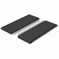
Philips Semiconductors 4. Ordering information Table 2: Type number GTL1655DGG TSSOP64 plastic thin shrink small outline package; 64 leads; Standard packing quantities and other packaging data are available at www.philipslogic.com/packaging. 4.1 Ordering options Table 3: Type number GTL1655DGG 9397 750 ...
Page 4
Philips Semiconductors 5. Pinning information 5.1 Pinning Fig 1. TSSOP64 pin configuration. 9397 750 12936 Product data 16-bit LVTTL-to-GTL/GTL+ bus transceiver with live insertion 1OEAB 1OEBA 2 63 1LEAB 1LEBA CC 1A1 4 61 ...
Page 5
Philips Semiconductors 5.2 Pin description Table 4: Symbol 1OEAB 1OEBA V CC 1A1 to 1A8 GND 2A1 to 2A8 2OEAB 2OEBA OE 2LEBA 2LEAB BIAS_V 2B8 to 2B1 V REF 1B8 to 1B1 V ERC 1LEBA 1LEAB CP 9397 750 ...
Page 6
Philips Semiconductors 6. Functional description Fig 2. Logic diagram. Fig 3. Logic diagram. 9397 750 12936 Product data 16-bit LVTTL-to-GTL/GTL+ bus transceiver with live insertion 41 V REF 61 V ERC 1LEAB 62 1LEBA 2 1OEBA 1 ...
Page 7
Philips Semiconductors 6.1 Function table Table 5: See Table note Inputs OEAB Table 6: See Table note Inputs Table 7: See Table note Input V Logic level ...
Page 8
Philips Semiconductors 7. Limiting values Table 8: Limiting values In accordance with the Absolute Maximum Rating System (IEC 60134). See Symbol Parameter V DC supply voltage CC BIAS V BIAS supply voltage CC I input clamping diode current IK V ...
Page 9
Philips Semiconductors 8. Recommended operating conditions Table 9: Recommended operating conditions Symbol Parameter BIAS V DC supply voltage CC V termination voltage TT V GTL reference voltage REF V input voltage i V HIGH-level input voltage IH V LOW-level input ...
Page 10
Philips Semiconductors 9. Static characteristics Table 10: DC characteristics +85 C; values otherwise stated V amb Symbol Parameter V input clamp voltage IK V HIGH-level output OH voltage V LOW-level output OL voltage I input ...
Page 11
Philips Semiconductors Table 10: DC characteristics …continued +85 C; values otherwise stated V amb Symbol Parameter I quiescent supply CC current I additional quiescent CC supply current per input pin; except port B C input ...
Page 12
Philips Semiconductors 10. Dynamic characteristics Table 12: Timing requirements over recommended supply voltage 0.8 V and REF ERC +85 C. amb Symbol Parameter Conditions t ...
Page 13
Philips Semiconductors Table 14: Port B to Port A switching 0.8 V for GTL (see TT REF +85 C. amb Symbol Parameter Conditions f maximum max frequency t B ...
Page 14
Philips Semiconductors Table 15: Timing requirements over recommended supply voltage and REF ERC +85 C. amb Symbol Parameter Conditions t pulse duration CP ...
Page 15
Philips Semiconductors Table 17: Port B to Port A switching for GTL+ (see Figures TT REF +85 C. amb Symbol Parameter Conditions f maximum max frequency t ...
Page 16
Philips Semiconductors LEAB 1.5 V 1.5 V input t t PLH W Port B V REF output Test condition: OEAB = Fig 8. LEAB to B propagation delay. Port ...
Page 17
Philips Semiconductors 11. Test information generator. Fig 15. Load circuitry for Port A output switching times generator. Fig 16. Load circuitry for Port B output switching times. 9397 750 12936 Product data 16-bit LVTTL-to-GTL/GTL+ ...
Page 18
Philips Semiconductors 12. Package outline TSSOP64: plastic thin shrink small outline package; 64 leads; body width 6 pin 1 index 1 e DIMENSIONS (mm are the original dimensions). A UNIT ...
Page 19
Philips Semiconductors 13. Soldering 13.1 Introduction to soldering surface mount packages This text gives a very brief insight to a complex technology. A more in-depth account of soldering ICs can be found in our Data Handbook IC26; Integrated Circuit Packages ...
Page 20
Philips Semiconductors • For packages with leads on two sides and a pitch (e): – larger than or equal to 1.27 mm, the footprint longitudinal axis is preferred to be parallel to the transport direction of the printed-circuit board; – ...
Page 21
Philips Semiconductors [3] These transparent plastic packages are extremely sensitive to reflow soldering conditions and must on no account be processed through more than one soldering cycle or subjected to infrared reflow soldering with peak temperature exceeding 217 C oven. ...
Page 22
Philips Semiconductors 15. Data sheet status [1] Level Data sheet status Product status I Objective data Development II Preliminary data Qualification III Product data Production [1] Please consult the most recently issued data sheet before initiating or completing a design. ...
Page 23
Philips Semiconductors Contents 1 Description . . . . . . . . . . . . . . . . . . . . . . . . . . . . . 1 2 Features . . . ...