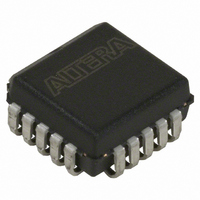
EPC1213LC20 Altera, EPC1213LC20 Datasheet - Page 48

EPC1213LC20
Manufacturer Part Number
EPC1213LC20
Description
IC CONFIG DEVICE 212KBIT 20-PLCC
Manufacturer
Altera
Series
EPCr
Datasheet
1.EPC4QI100N.pdf
(116 pages)
Specifications of EPC1213LC20
Programmable Type
OTP
Memory Size
212kb
Voltage - Supply
4.75 V ~ 5.25 V
Operating Temperature
0°C ~ 70°C
Package / Case
20-PLCC
For Use With
PLMJ1213 - PROGRAMMER ADAPTER 20 PIN J-LEAD
Lead Free Status / RoHS Status
Contains lead / RoHS non-compliant
Other names
544-2188-5
Available stocks
Company
Part Number
Manufacturer
Quantity
Price
Company:
Part Number:
EPC1213LC20
Manufacturer:
AT
Quantity:
23
Company:
Part Number:
EPC1213LC20
Manufacturer:
ALTERA
Quantity:
5 510
Company:
Part Number:
EPC1213LC20
Manufacturer:
TI
Quantity:
5 510
Part Number:
EPC1213LC20
Manufacturer:
ALTERA/阿尔特拉
Quantity:
20 000
2–12
Configuration Handbook (Complete Two-Volume Set)
1
1
The maximum boot file size for the EPC16 configuration device is 32K words or
64 Kbytes. The boot code is limited to the boot and flash memory parameter blocks.
When you select relative addressing mode for Main Block Data, the Quartus II
software aligns the last byte of information with the highest address (for example,
0x1FFFFF). Therefore, the starting address is dependent on the size of the .hex file.
You can easily obtain the starting address of the application code with the .map file
discussed in this section.
Conversely, the absolute addressing mode forces the Quartus II software to store the
boot or application .hex file data in address locations specified inside the .hex file
itself. When this mode is selected, create .hex files with the correct offsets and ensure
there is no overlap with addresses used for storing configuration data.
Figure 2–11
create a .pof and .map file for an enhanced configuration device.
Only one .hex file can be added to the Bottom Boot Data and Main Block Data
sections of this window.
Figure 2–11. Storing Boot and Application Code in Flash Memory
You can use the Quartus II Convert Programming Files window to create two files
specific to the external flash interface feature—the .hexout and the .map files. The
.hexout contains an image of the flash memory and the .map file contains memory
map information. The .hexout can be used by an external processor or PLD to
program the flash memory via the external flash interface. The .map file contains
starting and ending addresses for boot code, configuration page data, and application
code.
shows a screen shot of the Convert Programming Files window setup to
Chapter 2: Altera Enhanced Configuration Devices
© December 2009 Altera Corporation
External Flash Memory Interface


