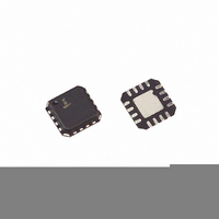
ISL6291-1CRZ Intersil, ISL6291-1CRZ Datasheet - Page 6

ISL6291-1CRZ
Manufacturer Part Number
ISL6291-1CRZ
Description
IC CHARGER LI-ION 4.1V 5X5 16QFN
Manufacturer
Intersil
Datasheet
1.ISL6291-1CRZ.pdf
(11 pages)
Specifications of ISL6291-1CRZ
Function
Charge Management
Battery Type
Lithium-Ion (Li-Ion), Lithium-Polymer (Li-Pol)
Voltage - Supply
4.35 V ~ 10 V
Operating Temperature
-20°C ~ 70°C
Mounting Type
Surface Mount
Package / Case
16-VQFN Exposed Pad, 16-HVQFN, 16-SQFN, 16-DHVQFN
Lead Free Status / RoHS Status
Lead free / RoHS Compliant
Functional Pin Description
VIN (Pin 1, 15, 16)
VIN is the input power source pin that is connected to a wall
adapter.
FAULT (Pin 2)
FAULT is an open-drain output indicating fault status. When
a fault condition occurs, this pin is pulled to LOW.
STATUS (Pin 3)
STATUS is an open-drain output indicating charging and
inhibit states. During any charge mode, this pin is pulled to
LOW.
TIME (Pin 4)
Connect a timing capacitor C
GND. The internal oscillator, as shown in the Block Diagram,
charges and discharges the timing capacitor between 0.5V
and 1.5V with 10
found as:
A 22-stage binary counter increments each oscillation period
to set up the TIMEOUT interval. The TIMEOUT interval can
be calculated as:
When the fast charge takes longer than the TIMEOUT
interval, or the Trickle charge time exceeds 1/8 of the
TIMEOUT interval, the charger issues a TIMEOUT fault
status and stops charging.
The oscillator also provides a time reference for the charger.
GND (Pin 5)
GND is the connection to system ground.
TOEN (Pin 6)
TOEN is the TIMEOUT enable input pin. Pulling this pin to
LOW disables the TIMEOUT charge-time limit for the fast
charge modes. Leave this pin floating to enable the
TIMEOUT limit. An internal 10µA pull-up circuit pulls this pin
up to a 2.8V internal reference. The trickle mode always has
the 1/8 TIMEOUT limited charge time regardless of this
input. When a TIMEOUT fault is issued, the charger is
latched. The only way to enable the charger again is to cycle
the input power, or to toggle the EN pin.
EN (Pin 7)
EN is the CMOS logic input. Leave this pin floating to enable
the charger. This pin is pulled up to the internal 2.8V
reference via a 10µA current source.
T
TIMEOUT
OSC
=
0.2 10
=
⋅
2
22
6
µ
⋅
⋅
C
A current. The oscillation period can be
T
TIME
OSC
=
14
⋅
TIME
(
C
----------------- -
sec
6
1nF
TIME
onds
between this pin and
)
(
minutes
)
V2P8 (Pin 8)
V2P8 is a 2.8V reference voltage output. V2P8 pin outputs a
2.8V voltage when the input voltage rises above the POR
threshold and outputs zero voltage otherwise. This pin can
be used as an adapter presence signal. A 0.1µF Ceramic
capacitor is recommended for decoupling purposes. This pin
can be used to bias other circuits with a maximum current of
2mA.
IREF (Pin 9)
IREF is the programming input for the constant charge
current. Connect a resistor R
Application) to this pin. The voltage of this pin is regulated to
a 0.8V reference voltage. The charging current during the
constant current mode charge is 100,000 times of the
current in the R
constant current mode can be found as:
where V
IMIN (Pin 10)
IMIN is a programmable input for the end-of-charge current.
The pin voltage is also regulated at 0.8V. The end-of-charge
current can be found as:
TEMP (Pin 11)
TEMP is an Input for an external NTC thermistor. As shown
in the Block Diagram, two comparators forms a window
comparator with its low and high thresholds set by V
and V
is outside the window, the charger stops. When the TEMP
pin voltage falls back into the window, the charger starts a
new charge cycle. The V
determined by the internal resistor divider, as shown in the
block diagram. See “Battery Pack Temperature Monitoring”
for more information.
The TEMP pin is also used for battery removal detection. It
is assumed that the thermistor is co-packed with the battery.
When the charger sees a TEMP pin voltage that is 2.1V or
higher, it assumes that the battery is removed. When a
battery is removed, a FAULT signal is indicated and charging
is halted. When a battery is inserted again, a new charge
cycle starts.
VBAT (Pin 12, 13, 14)
VBAT is the connection to a battery. Typically a 10µF
Tantalum capacitor is needed for stability when no battery is
attached to this pin. When a battery is connected, however,
no capacitor is required for stability. A 0.1µF ceramic
capacitor is recommended for decoupling.
I
I
REF
MIN
=
=
TMAX
10000
100000
REF
respectively. When the voltage on the TEMP pin
is the 0.8V reference voltage.
⋅
----------------
R
V
⋅
IREF
---------------- -
R
IMIN
REF
V
IREF
REF
=
resistor. The charging current in the
=
----------------
R
0.8V
IMIN
---------------- -
R
TMIN
0.8V
IREF
×10 A
IREF
and V
×10 A
4
( )
5
(see the Typical
( )
TMAX
voltage is
May 2, 2005
TMIN
FN9102.2


