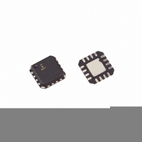
ISL6291-1CRZ Intersil, ISL6291-1CRZ Datasheet - Page 9

ISL6291-1CRZ
Manufacturer Part Number
ISL6291-1CRZ
Description
IC CHARGER LI-ION 4.1V 5X5 16QFN
Manufacturer
Intersil
Datasheet
1.ISL6291-1CRZ.pdf
(11 pages)
Specifications of ISL6291-1CRZ
Function
Charge Management
Battery Type
Lithium-Ion (Li-Ion), Lithium-Polymer (Li-Pol)
Voltage - Supply
4.35 V ~ 10 V
Operating Temperature
-20°C ~ 70°C
Mounting Type
Surface Mount
Package / Case
16-VQFN Exposed Pad, 16-HVQFN, 16-SQFN, 16-DHVQFN
Lead Free Status / RoHS Status
Lead free / RoHS Compliant
Charge Termination Voltage Regulation
As the battery voltage rises to the 4.1V or 4.2V termination
voltage, the voltage amplifier starts to output positive voltage
and to source current. This current partially cancels the
current of the reference current I
current. If the battery voltage increases further due to the
charging, the voltage amplifier increases its output current to
reduce the equivalent reference current. As a result, after the
battery voltage reaches the termination voltage, the charge
current starts to decrease.
As the charging current drops to the end-of-charge current
level programmed by the IMIN pin, the charge stops. The
large voltage control loop gain guarantees that the battery
voltage is regulated within the 1% error specification.
Internal Thermal Management
The temperature rise of a linear charger is always a concern
in real applications. The temperature rise is caused by the
power dissipation of the charger. Maximum power
dissipation occurs when the battery is charged in the
constant current mode. The advanced thermal management
function of the ISL6291 frees users from the temperature
rise concern. The ISL6291 adopts a current-foldback
technique against the temperature rise. Under normal
operation, the ISL6291 charges the battery with the
programmed I
detects 100°C temperature in the IC, it starts to reduce the
charge current to prevent further temperature rise. The gain
for the current-foldback is 40mA/°C (or 0.4µA°C for the
reference current I
100°C; therefore, for a charger with the constant charge
current set at 1A, the charge current is reduced to zero when
the internal temperature rises to 125°C. The actual internal
temperature should settle between 100°C to 125°C,
depending on the operating conditions, if the temperature
does rise above 100°
Battery Pack Temperature Monitoring
The ISL6291 uses two comparators to form a window
comparator. Figure 3 shows the internal circuit. When the
TEMP pin voltage is “out of the window,” as determined by
the V
MOSFETs, Q1 and Q2, produce hysteresis for both upper
and lower threshold. Figure 4 shows all the critical voltage
levels and the output of the two comparators versus the
TEMP pin voltage.
The external thermistor circuit is shown in Figure 3. The NTC
thermistor R
resistive divider. R
pin. Assume the resistance of the NTC thermistor is R
the high temperature limit, and is R
be shown that:
R
TL
=
TMIN
9 R
⋅
and V
TH
T
REF
requires a pull-up resistor R
TMAX
. If the internal thermal monitoring circuit
U
R
) after the internal temperature reaches
should be pulled up to the 2.8V V2P8
C
, the charging is stopped. The two
.
9
R
to reduce the charge
TL
at the low limit. It can
U
to form a
TH
at
Select an NTC thermistor whose resistance value satisfies
the above equation. A curve-1 NTC thermistor from Vishay is
a good candidate for this application. If a thermistor does not
meet this requirement, using a resistor in parallel or series
with the thermistor may solve the problem. Once the
thermistor is selected, the pull-up resistor should be chosen
as:
If a parallel or series resistor is used, the R
combined value at the low temperature limit. The
temperature hysteresis can be calculated once the thermistor
is selected. The typical hysteresis is about 3°C to 5°C.
FIGURE 3. THE INTERNAL AND EXTERNAL CIRCUIT FOR THE
R
U
FIGURE 4. CRITICAL VOLTAGE LEVELS FOR TEMP PIN
Under
Temp
Over
Temp
=
R
V
V
TL
TMAX+
TMAX
V
V
ISL6291
TMIN-
TMIN
CP1
BATTERY PACK TEMPERATURE MONITORING
CP2
Voltage
TEMP
(0.28V)
(0.33V)
Under
Temp
Temp
Pin
Over
2.8V
(1.2V)
(1.4V)
+
+
-
-
0V
V
TMAX
V
To TEMP Pin
TMIN
Q1
Q2
2.8V
R2
75K
R5
4K
R4
20K
R1
100K
R3
5K
TL
V2P8
TEMP
GND
value is the
May 2, 2005
R
R
T
FN9102.2
U


