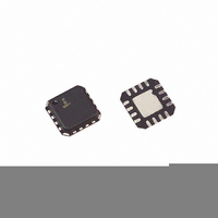
ISL6291-1CRZ Intersil, ISL6291-1CRZ Datasheet - Page 7

ISL6291-1CRZ
Manufacturer Part Number
ISL6291-1CRZ
Description
IC CHARGER LI-ION 4.1V 5X5 16QFN
Manufacturer
Intersil
Datasheet
1.ISL6291-1CRZ.pdf
(11 pages)
Specifications of ISL6291-1CRZ
Function
Charge Management
Battery Type
Lithium-Ion (Li-Ion), Lithium-Polymer (Li-Pol)
Voltage - Supply
4.35 V ~ 10 V
Operating Temperature
-20°C ~ 70°C
Mounting Type
Surface Mount
Package / Case
16-VQFN Exposed Pad, 16-HVQFN, 16-SQFN, 16-DHVQFN
Lead Free Status / RoHS Status
Lead free / RoHS Compliant
Description
Initialization
The ISL6291 initializes as the input voltage rises above the
power-on-reset (POR) threshold. Once the input voltage
reaches the POR level, the V2P8 pin outputs a 2.8V voltage.
This output voltage can be used as an adapter presence
indication and to bias the thermistor circuit. The POR takes
about 200µs. During the POR, the STATUS pin outputs a
logic HIGH signal, and the FAULT pin outputs a logic LOW
signal.
Operation States
Immediately after the POR, the charger enters a charge
state. A charge state always cycles through a trickle mode, a
constant-current mode, and a constant voltage mode, as
shown in Figure 1. If the battery completes a charge cycle
without a fault, the operation moves to the inhibit state,
waiting for the battery to be discharged to start another
charge cycle. Two types of fault may occur during a charge
cycle, namely, a TIMEOUT fault or a temperature fault (refer
to Functional Pin Description on TIME, TOEN, and TEMP
pins). If a fault occurs during the charge modes, the
operation enters the fault state. The charger is in a standby
state when the adapter is removed, or the EN pin of the IC is
pulled to LOW. In the standby state, the charger IC draws
less than 1
pins, STATUS and FAULT, indicate the operation states of
the charger (see Table 1).
HIGH
HIGH
LOW
*Both outputs are pulled up with external resistors.
FAULT
HIGH
LOW
HIGH
STATUS
µ
A current from the battery. The two open-drain
TABLE 1. STATUS INDICATIONS
Charge completed with no fault (Inhibit) or
Standby
Charging in one of the three modes
Fault
V
RECHRG
V
V
MIN
CH
0
7
< 1/8 TIMEOUT
Trickle time
INDICATION
Trickle
Mode
Constant Current
FIGURE 1. MODES OF OPERATION
Mode
Constant Voltage
Mode
TIME
TIMEOUT
The charger starts a new charge cycle when a wall adapter
is plugged in, a new battery is inserted, a battery voltage
drops below the re-charge threshold, a temperature fault
ends, or the EN pin is toggled from LOW to HIGH.
Trickle Charge Mode
A charge cycle always starts with the trickle charge mode.
The trickle charge mode is to pre-condition the battery and
prepare it for the fast charge (constant current or constant
voltage charge). It is not recommended to fast charge a
Li-ion battery when the battery is deeply discharged,
indicated by a low battery voltage. When the ISL6291 sees a
battery voltage lower than the V
Specifications, it forces 1/10 of the current in the constant
current mode into the battery. The charger stays in the trickle
mode until the battery voltage is above V
consecutive oscillation cycles (T
to avoid entering the constant current mode accidentally,
caused by any transient voltage spike on the battery pack
terminals. The charge time for the trickle mode is limited to
1/8 of the TIMEOUT interval (see TIME pin description and
Figure 1). If the trickle charge time takes longer than 1/8 of
the TIMEOUT interval, a TIMEOUT fault is issued and the
charger is latched. The minimum trickle charge time is 15
T
trickle mode, the STATUS pin is set to logic LOW, and the
FAULT pin is set to logic HIGH.
Constant Current Charge Mode
The battery is charged with a constant current programmed
by the IREF pin resistor (see IREF pin description) during
the constant current mode. The constant current is trimmed
to 10% accuracy. The battery voltage rises towards the
charge termination voltage V
current mode ends when the battery voltage reaches V
The internal clock counter limits the maximum time for the
constant current mode to the TIMEOUT interval. The counter
is reset at the beginning of the this charge mode. If the
OSC,
and the maximum time is 1/8 TIMEOUT. During the
Inhibit
Trickle
Mode
Mode
CC
Mode
CV
CH
I
I
MIN
I
0
REF
OSC
MIN
in this mode. The constant
REF
/10
given in the Electrical
). The 15-cycle delay is
MIN
for 15
May 2, 2005
FN9102.2
CH
.


