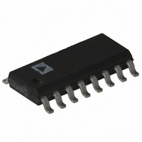
ADE7769AR Analog Devices Inc, ADE7769AR Datasheet

ADE7769AR
Specifications of ADE7769AR
Available stocks
Related parts for ADE7769AR
ADE7769AR Summary of contents
Page 1
FEATURES On-chip oscillator as clock source High accuracy, supports 50 Hz/60 Hz IEC62053-21 Less than 0.1% error over a dynamic range of 500 to 1 Supplies average real power on frequency outputs F1 and F2 High frequency output CF calibrates ...
Page 2
ADE7769 TABLE OF CONTENTS Specifications..................................................................................... 3 Timing Characteristics ................................................................ 4 Absolute Maximum Ratings............................................................ 5 ESD Caution.................................................................................. 5 Terminology ...................................................................................... 6 Pin Configuration and Function Descriptions............................. 7 Typical Performance Characteristics ............................................. 8 Functional Description .................................................................. 10 Theory of Operation .................................................................. 10 ...
Page 3
SPECIFICATIONS ± 5%, AGND = DGND = 0 V, on-chip reference, RCLKIN = 6.2 kΩ, 0.5% ± 50 ppm/° unless otherwise noted. Table 1. Parameter , ACCURACY Measurement Error on Channel ...
Page 4
ADE7769 Parameter POWER SUPPLY See the Terminology section for an explanation of specifications. 2 See the figures in the Typical Performance Characteristics section. 3 Sample tested during initial release and after any redesign or process ...
Page 5
ABSOLUTE MAXIMUM RATINGS T = 25°C, unless otherwise noted. A Table 3. Parameter V to AGND DGND DD Analog Input Voltage to AGND, V1P, V1N, V2P, and V2N Reference Input Voltage to AGND Digital Input Voltage to ...
Page 6
ADE7769 TERMINOLOGY Measurement Error The error associated with the energy measurement made by the ADE7769 is defined by the following formula: Energy Registered by ADE7769 = %Error True Energy Phase Error Between Channels The high-pass filter (HPF) in the current ...
Page 7
PIN CONFIGURATION AND FUNCTION DESCRIPTIONS Table 4. Pin Function Descriptions Pin No. Mnemonic Description 1 V Power Supply. This pin provides the supply voltage for the circuitry in the ADE7769. The supply voltage DD should be maintained ...
Page 8
ADE7769 TYPICAL PERFORMANCE CHARACTERISTICS 220V 40A TO 1 0.8 ON-CHIP REFERENCE 0.6 0.4 0.2 +25°C 0 –0.2 –0.4 –0.6 –0.8 –1.0 0.1 1 CURRENT CHANNEL (% of Full Scale) Figure 5. Error Reading ...
Page 9
PF = 0.5 IND 0.1 0 –0.1 –0 0.5 CAP –0.3 –0.4 –0 FREQUENCY (Hz) Figure 9. Error Reading over Input Frequency 1.0 ...
Page 10
ADE7769 FUNCTIONAL DESCRIPTION THEORY OF OPERATION The two ADCs in the ADE7769 digitize the voltage signals from the current and voltage sensors. These ADCs are 16-bit Σ-Δs with an oversampling rate of 450 kHz. This analog input structure greatly simplifies ...
Page 11
sin hω t β ≠ where: i(t) is the instantaneous current the dc component the rms ...
Page 12
ADE7769 ±165mV >> NEUTRAL PHASE Figure 20. Typical Connections for Channel V2 POWER SUPPLY MONITOR The ADE7769 contains an on-chip power supply monitor. ...
Page 13
FREQUENCY (Hz) Figure 24. Phase Error Between Channels ( Hz) Digital-to-Frequency Conversion As previously described, the digital output of the low-pass filter after multiplication ...
Page 14
ADE7769 CF FREQUENCY RIPPLE AVERAGE FREQUENCY TIME ADE7769 CF Figure 26. Interfacing the ADE7769 to an MCU As shown in Figure 26, the frequency output, CF, is connected to an MCU counter or port. This counts the number of pulses ...
Page 15
Table 5. F Frequency Selection 1– OSC Relation F at Nominal OSC (Hz) 1– OSC/2 0. OSC/2 1. OSC/2 3. OSC/2 6. ...
Page 16
... An evaluation board can be used to verify the functionality and the performance of the ADE7769. Download the documenta- tion for the board from In addition, the reference design board ADE7769ARN-REF and Application Note AN-679 can be used in the design of a low cost watt-hour meter that surpasses IEC62053-21 accuracy specifications ...
Page 17
... Model Temperature Range ADE7769AR −40°C to +85°C ADE7769AR-RL −40°C to +85°C 1 ADE7769ARZ −40°C to +85°C 1 ADE7769ARZ-RL −40°C to +85°C EVAL-ADE7769EB ADE7769AR-REF Pb-free part. 10.00 (0.3937) 9.80 (0.3858 6.20 (0.2441) 4.00 (0.1575) 5.80 (0.2283) 3.80 (0.1496 1.75 (0.0689) 1 ...
Page 18
ADE7769 NOTES Rev Page ...
Page 19
NOTES Rev Page ADE7769 ...
Page 20
ADE7769 NOTES © 2005 Analog Devices, Inc. All rights reserved. Trademarks and registered trademarks are the property of their respective owners. D05332–0–8/05(A) Rev Page ...


