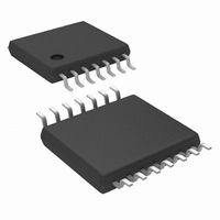
LM3429MH/NOPB National Semiconductor, LM3429MH/NOPB Datasheet - Page 9

LM3429MH/NOPB
Manufacturer Part Number
LM3429MH/NOPB
Description
IC LED DRVR HP CONS CURR 14TSSOP
Manufacturer
National Semiconductor
Series
PowerWise®r
Type
High Power, Constant Currentr
Datasheet
1.LM3429MHNOPB.pdf
(34 pages)
Specifications of LM3429MH/NOPB
Constant Current
Yes
Topology
PWM, SEPIC, Step-Down (Buck), Step-Up (Boost)
Number Of Outputs
1
Internal Driver
No
Type - Primary
Automotive
Type - Secondary
High Brightness LED (HBLED)
Frequency
2MHz
Voltage - Supply
4.5 V ~ 75 V
Mounting Type
Surface Mount
Package / Case
14-TSSOP Exposed Pad, 14-eTSSOP 14-HTSSOP
Operating Temperature
-40°C ~ 125°C
Current - Output / Channel
1A
Internal Switch(s)
No
Efficiency
95%
For Use With
LM3429BSTEVAL - BOARD EVAL FOR BOOST LM3429LM3429BKBSTEVAL - BOARD EVAL FOR BUCK-BOOST LM3429
Lead Free Status / RoHS Status
Lead free / RoHS Compliant
Voltage - Output
-
Other names
LM3429MH
Available stocks
Company
Part Number
Manufacturer
Quantity
Price
Adding a PNP transistor as shown in
constant ripple over varying V
The switching frequency is defined:
Buck (Constant Ripple vs. V
Buck (Constant Ripple vs. V
Boost and Buck-boost
For all topologies, the C
1 nF and should be located very close to the LM3429.
FIGURE 3. Off-timer Circuitry for Buck Regulators
T
capacitor is recommended to be
O
IN
O
.
)
)
Figure 3
FIGURE 4. LED Current Sense Circuitry
will provide
300944a0
9
AVERAGE LED CURRENT
The LM3429 uses an external current sense resistor (R
placed in series with the LED load to convert the LED current
(I
and HSN pins are the inputs to the high-side sense amplifier
which are forced to be equal potential (V
negative feedback. Because of this, the V
across R
out of the CSH pin and through the R
amplifier will regulate the CSH pin to 1.24V, therefore I
be calculated:
This means V
I
The selection of the three resistors (R
not arbitrary. For matching and noise performance, the sug-
gested signal current I
current does not flow in the LEDs and will not affect either the
off state LED current or the regulated LED current. I
be above or below this value, but the high-side amplifier offset
characteristics may be affected slightly. In addition, to mini-
mize the effect of the high-side amplifier voltage offset on LED
current accuracy, the minimum V
50 mV. Finally, a resistor (R
series with the HSN pin to cancel out the effects of the input
bias current (~10 µA) of both inputs of the high-side sense
amplifier. Note that he CSH pin can also be used as a low-
side current sense input regulated to the 1.24V. The high-side
sense amplifier is disabled if HSP and HSN are tied to GND.
LED
LED
can then be calculated:
) into a voltage (V
HSP
to generate the signal current (I
SNS
will be regulated as follows:
SNS
CSH
) as shown in
HSN
is approximately 100 µA. This
= R
SNS
HSP
30094457
SNS
CSH
) should be placed in
is suggested to be
SNS
, R
Figure
HSP
resistor. The error
CSH
CSH
voltage is forced
=V
, and R
) which flows
HSN
4. The HSP
www.national.com
) through
CSH
CSH
HSP
SNS
can
can
) is
)


